40 co3+ orbital diagram
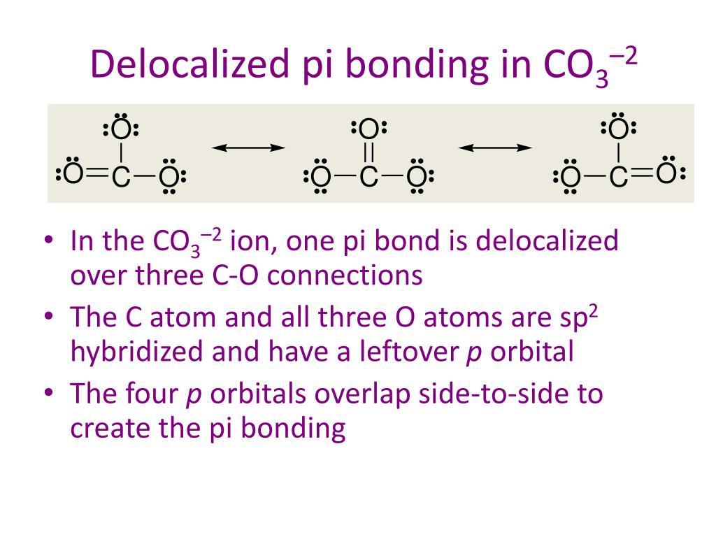
Solution for Show the molecular orbital diagram for the π bonds in the carbonate anion (CO3^2−). What is the connection order π? a) Differentiate b) Atomic… NCERT Exemplar Solutions Class 11 Chemistry Chapter 4 – Free PDF Download. NCERT Exemplar Chemistry Class 11 Chapter 4 Chemical Bonding and Molecular Structure is provided here to help students develop a clear approach to chemical bonding. Chemical Bonding and Molecular Structure is a very important topic that lays the foundation for all your future studies.
12-12 This video describes the molecular orbital theory diagram of CO, placing emphasis on how MO theory differs for homo and heteronuclear diatomics

Co3+ orbital diagram
Transcribed image text: Draw an orbital diagram for the Zn2+, Cu2+, Co2+, Fe2+, Fe3+, and Cr3+ ions in the presence of solvent molecules. Use up and down arrows to represent the spin of electrons. Only two electrons can occupy a single box. Fill the lower three boxes before filling the upper two and make sure to follow Hund's rule as you fill the orbitals with electrons. (a) Co3+ valence orbitals; (b) oxygen valence orbitals; (c) standard MO diagram of CoO6. 654 K.M.E. MmDZt~qSKA et al. metal and the group of ligands may interact. For Co304 this calculation is most conveniently carried out in two steps; first the [Co2+O42-] unit can be defined and then six such units are used as ligands for the Co3+ ion. Academia.edu is a platform for academics to share research papers.
Co3+ orbital diagram. Cobalt has a total of 27 electrons which are contained in 1s 2s 2p 3s 3p 4s and 3d sub. Orbital diagram of cobalt an orbital diagram is a way of showing where and how many electrons are in an atom of a certain element. The orbital diagram for the atom of cobalt is shown below. 1s2 2s2 2p1 boron 1s2 2s2 2p6 3s2 3p6 4s2 3d1. So these are orbital's. And we will mention the end. Well, sure mentioned the electrons here. P or written, is two electrons. So first we will single field 2 2 electrons. And what orbital here is a new hybridized. This is um, hi brie diced mm pick. So so this is a orbital diagram of carbon in so to an indication of carbon atoms electrons in ... Molecular Orbital Diagram of CO. By. All About Chemistry - July 2, 2020. 1. 236. Molecular Orbital Diagram of CO. TAGS; Molecular Orbital Diagram; Previous article Wohl-Ziegler Bromination. Next article Molecular Orbital Diagram of NO. All About Chemistry. https://allaboutchemistry.net. Hello Reader! Thanking for reading this post, If you find ... electrons into the same orbital •Πeis a stabilizing energy for electron exchange associated with two degenerate electrons having parallel spin total 3 e 0 c eg* t2g d4HS eg* t2g d8 eg* t2g d6LS total 7 e 3 c total 6 e 3 c LFSE 3 0.4 O 10.6 O 0.6 O LFSE 6 0.4 O 20.6 O
To write the configuration for the Cobalt ions, first we need to write the electron configuration for just Cobalt (Co). We first need to find the number of ... Visualizing the 3F and 3P States (see Table 2.3) 3F is the ground state with 21 microstates • One electron into each orbital places them as far apart as possible • For these seven orbital combinations remember that there will be M S = +1, 0, -1 microstates 3P is the spin-allowed excited state with 9 microstates • These microstates put the electrons in the same plane, resulting in greater Answer (1 of 12): You have hit on the biggest change in the Period Table of Elements in the last decade. This is an intense debate, forgive me intensity because the winner gets the prize. Changing the aufbau filing is historic. The strict aufbau filling would say that electrons fill 2 x s, 6 x p... CO32- Molecular Orbital (MO) Diagram What is MO theory? Molecular Orbital Theory is a concept of quantum mechanics that is used to decipher the chemical bonding nature inside different molecular structures. This is a complex yet useful tool that helps in sketching MO diagrams for better understanding.
what does a valence orbital diagram look like? Place the following elements in order of increasing atomic radius P Ba Cl . Cl < P < Ba. Give the ground state electron configuration for Rb⁺. [Ar]4s²3d¹⁰4p⁶. Give the set of four quantum numbers that could represent the last electron added (using the Aufbau principle) to the Cl atom. n = 3, l = 1, ml =1, ms = +1/2. Hund's Rule. … 1. (a) Construct a pi molecular orbital energy level diagram for the allyl cation (𝐶𝐶. 3. 𝐻𝐻. 5+). Label the HOMO and LUMO. Hint: You drew pictures of all the π MOs in question 2 of Exercise 4.3. (b) Based on your pi molecular orbital energy level diagram and on the pictures of the π MOs molecular orbital diagram as a non-bonding molecular orbital. 7. There are a total of 6 electrons to add to the molecular orbital diagram, 3 from boron and 1 from each hydrogen atom. sp Hybrid Orbitals in BeH2 1. The Lewis structure shows that the beryllium in BeH 2 makes 2 bonds and has no lone pairs. It is a Molecular Orbital Energies. The orbital energies are given in eV, where 1 eV=96.49 kJ/mol. Orbitals with very low energy are core 1s orbitals. More antibonding orbitals than you might expect are sometimes listed, because d orbitals are always included for heavy atoms and p orbitals are included for H atoms.
C) When two atomic orbitals come together to form two molecular orbitals, one molecular orbital will be lower in energy than the two separate atomic orbitals and one molecular orbital will be higher in energy than the separate atomic orbitals. D) Electrons placed in antibonding orbitals stabilize the ion/molecule. E) All of the above are true.
Orbital Diagram 1s ↿⇂ 2s ↿⇂ 2p ↿⇂ ↿⇂ ↿⇂ 3s ↿⇂ 3p ↿⇂ ↿⇂ ↿⇂ 3d ↿⇂ ↿⇂ ↿⇂ ↿⇂ ↿⇂ 4s ↿⇂ 4p ↿⇂ ↿ ↿ 4d 4f: ... The electron configuration of Co3+ is [Ar]4s3d5 . Co is in Period 4 of the Periodic Table, ...
Phase diagram of single component system (Water) Phase diagram of binary Eutectic System ( Cu-Ag.) Corrosion: Types, Mechanisms & prevention. UNIT 6: Spectroscopic techniques and application Principle, Instrumentation & Applications, electronics spectroscopy, Vibrational & Rotational Spectroscopy of diatomic molecules. UNIT 7: Periodic properties Effective Nuclear …
MOLECULAR ORBITAL APPROACH Basis of VB approach: overlap orbitals in each bond separately. Each bond is LOCALISED between two atoms. In molecular orbital (MO) approach - overlap orbitals for the whole molecule - bonding is therefore DELOCALISED. We will look first at DIATOMIC MOLECULES and only later move on to POLYATOMIC MOLECULES.
Chemistry. Chemistry questions and answers. What is the molecular orbital diagram for a carbonate ion? CO3 2- Please include labels for the orbitals like T2g, pi, pi anti-bonding etc. Question: What is the molecular orbital diagram for a carbonate ion?
3. 3+Using your answer from Question 2, draw a d-orbital splitting diagram for low-spin Co similar to the one given for Cr3+ 3+in the introduction to this experiment. Almost all Co complexes are low-spin, with a minimum number of unpaired electrons. (Refer to your text for further explanation.) 4.
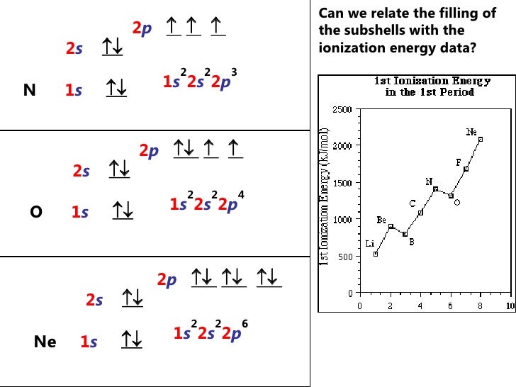
By Hund's rule, the electron configuration of carbon, which is 1s2 2s2 2p2, is understood to correspond to the orbital diagram shown in c. Experimentally, it is found that the ground state of a neutral carbon atom does indeed contain two unpaired electrons. Which of the following has maximum number of unpaired electrons fe3+ Fe2+ Co2+ Co3 ...
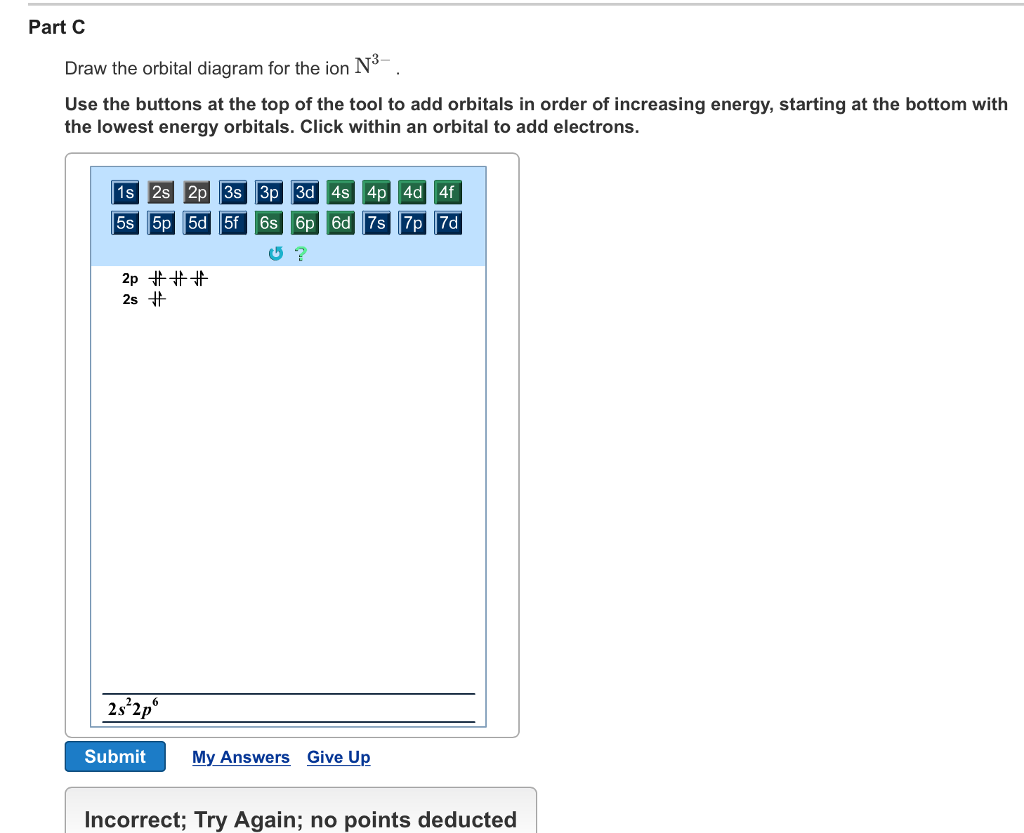
Part B. Draw the orbital diagram for the ion Co2+. Use the buttons at the top of the tool to add orbitals in order of increasing energy, starting at. Ni2+ Draw the d-orbital splitting diagrams for the octahedral complex ions of each of the following. a. Zn2+ b. Co2+ (high and low spin) c. Ti3+ the FT ligand.
14.12.2021 · Two molecules of ethylene (C2H4) can be incorporated via a radical mechanism. An automated computing system can control the reaction tank producing the desired product (yellow colored tank). The reaction quickly takes place under irradiation from blue LED panels installed on the bottom of the tanks. View the article.
Jan 03, 2016 · The electron configuration of Co3+ is [Ar]4s3d5. Co is in Period 4 of the Periodic Table, and Ar is the preceding noble gas. Cobalt is also in Group 9, so it must have 9 valence electrons. The valence shell configuration is therefore 4s23d7, and the core notation is. When a transition metal forms an ion, the s electrons are removed before the d ...
A molecular orbital diagram, or MO diagram, is a qualitative descriptive tool explaining chemical bonding in molecules in terms of molecular orbital theory in general and the linear combination of atomic orbitals (LCAO) method in particular. A fundamental principle of these theories is that as atoms bond to form molecules, a certain number of atomic orbitals combine to form the same number of ...
Atomic Orbital Diagram for Cobalt (Co) Cobalt ion (Co 2+ ,Co 3+ )electron configuration Ground state electron configuration of cobalt (Co) is 1s 2 2s 2 2p 6 3s 2 3p 6 3d 7 4s 2. The electron configuration shows that the last shell of cobalt has two electrons and the d-orbital has a total of seven electrons.
Get 24⁄7 customer support help when you place a homework help service order with us. We will guide you on how to place your essay help, proofreading and editing your draft – fixing the grammar, spelling, or formatting of your paper easily and cheaply.
orbital theory, is commonly used. It is often difficult for students to grasp these seemingly abstract theories without concrete evidence. Electronic and orbital changes occur when a ligand binds to a transition metal. These electronic changes are manifested in the splitting of the metal d orbitals during complex formation
Academia.edu is a platform for academics to share research papers.
Get the detailed answer: Depict the electron configurations for V2+, V3+, and Co3+. Use the orbital box diagram and noble gas notation. Are any of the ions
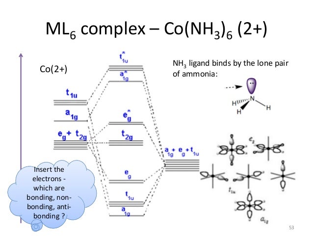
The overall molecular orbital energy level diagram for σ-bonding in octahedral complexes can be shown as: Figure 10. The formation of σ-molecular orbitals (bonding, antibonding and non-bonding) in octahedral complexes of transition metals. Buy the complete book with TOC navigation,
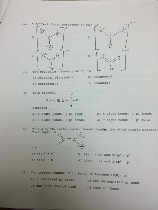
Carbonate Ion is a polyatomic ion with formula of CO3 (2-). Carbonate is a carbon oxoanion. It is a conjugate base of a hydrogencarbonate. Salts or ions of the theoretical carbonic acid, containing the radical CO2 (3-). Carbonates are readily decomposed by acids.
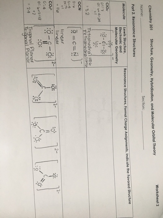
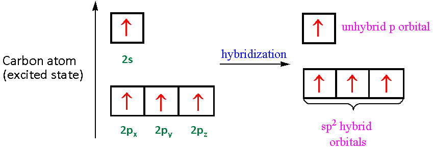
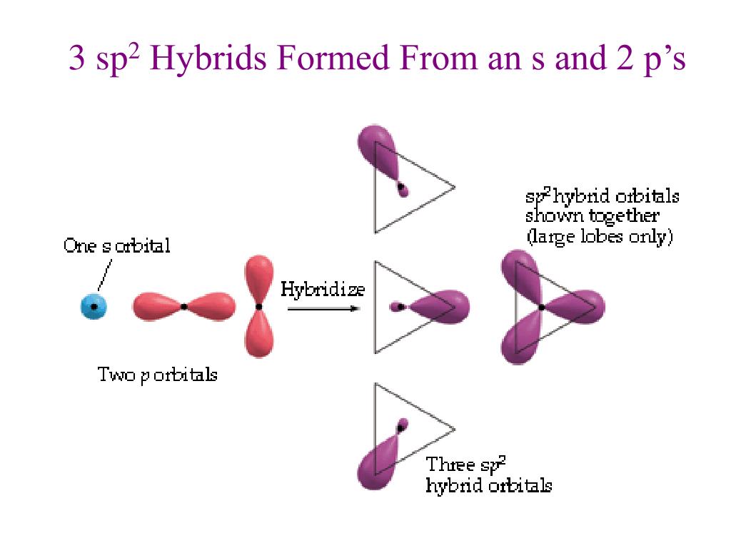
For the carbonate ion, CO3 2−. 1- Draw the electron orbital diagram for the valence electrons of the central carbon. before and after hybridization. 2- Identify which carbon and oxygen electron orbitals overlap to create each single and double C-O bond in the structure. check_circle.
Academia.edu is a platform for academics to share research papers.
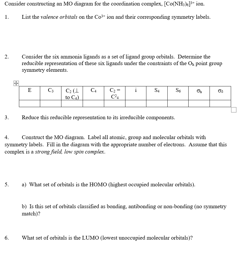
(a) Co3+ valence orbitals; (b) oxygen valence orbitals; (c) standard MO diagram of CoO6. 654 K.M.E. MmDZt~qSKA et al. metal and the group of ligands may interact. For Co304 this calculation is most conveniently carried out in two steps; first the [Co2+O42-] unit can be defined and then six such units are used as ligands for the Co3+ ion.
Transcribed image text: Draw an orbital diagram for the Zn2+, Cu2+, Co2+, Fe2+, Fe3+, and Cr3+ ions in the presence of solvent molecules. Use up and down arrows to represent the spin of electrons. Only two electrons can occupy a single box. Fill the lower three boxes before filling the upper two and make sure to follow Hund's rule as you fill the orbitals with electrons.
















Comments
Post a Comment