42 map sensor wiring diagram
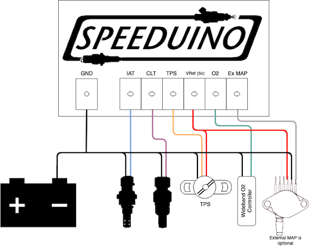
Wiring and Datasheets Resources. Map Sensor Wiring Diagram. Throttle Position Sensor TPS Manifold Absolute Pressure MAP Sensor Engine Coolant Temperature ECT Sensor Intake Air Temperature IAT Sensor and the Vehicle Speed. Map Sensor Wiring Diagram wiring diagram is a simplified tolerable pictorial representation of an electrical circuitIt shows the components of the circuit as simplified shapes and the capability and signal friends amid the devices. Otherwise the structure wont work as it ought to be.
Map Sensor Wiring Diagram. S60 automobile pdf manual download. C6 TechPerformance - cam sensor connector wiring - If any one out of the engine harness and plugs into the cam sensor jumper harness.
Map sensor wiring diagram
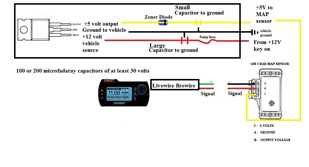
User manual | 3Bar Map Sensor Wiring Diagram. Twin Tec 3BarGuide Map Sensor Installation CAUTION: CAREFULLY READ INSTRUCTIONS Cable drive applications would install in the same fashion but will not have an IAT signal wire. Keep the vacuum line as short as possible and route... Issue Wiring In Gm Map Sensor For Lw. Wiring Diagram 2011 Hyundai Sonata Map Sensor Connector. 1993. Repair Guides. Iac Valve Wiring Diagrams. Wiring Diagram 2011 Hyundai Sonata Map Sensor Connector. Motiv 750 Port Injection W Aem Ems4 Progress Thread. Obd1 map sensor wiring diagram. Soarer wiring diagrams Wiring diagrams for your Toyota Soarer. Architectural wiring diagrams proceed the approximate locations and interconnections of receptacles lighting and enduring electrical services in a building.
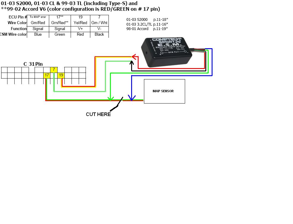
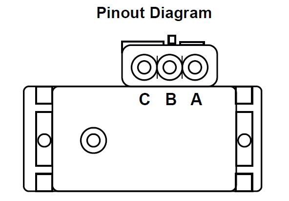
Map sensor wiring diagram. MAP sensor wiring diagram - SL2 Saturn Cars & Trucks. If you purchase a haines of chiltons manual ($25 in a retail store or $18 on amazon), it will have a detailed wiring diagram of the MAP sensor. For the MAP sensor you can test the wires with a multimeter... it will be obvious which ones are ground and +5v. looking into the stock map sensor (not the plug) the left one is ground and the right is the power supply which leaves the middle as the signal. Map Sensor Wiring Diagram- wiring diagram is a simplified tolerable pictorial representation of an electrical circuit. It shows the components of the circuit as simplified shapes, and the capability and signal friends amid the devices. Wiring Diagram Map Sensor Honda. Pin On Crank Sensor Test. How a car starting system works: system diagram, starter motor, solenoid, starter relay, neutral safety switch.
Note that the external wiring diagram in this Sensors and Wiring section is entirely separate from, though similar to, the Relay Board. MAP Sensor. The most fundamental measurement MegaSquirt® EFI controller uses to determine the amount of fuel to inject is the manifold absolute pressure. «Map sensor diagram»: The MAP sensor is normally accessible and quite easy to remove and reinstall. How long does a map sensor last? Question from categories: ford map sensor location map sensor diagram map sensor testing map sensor wiring diagram faulty map sensor symptoms. Map Sensor Wiring Diagram - Map wiring diagram here need a bit of help maybe you should measure the voltage between each of the two pins and the ground. Pin 2 signal green. Interconnecting wire routes may be shown approximately where particular receptacles or fixtures must be on a... MAP Sensor & Wiring Diagram. Смотреть позже. Поделиться.
MAP Sensor & Wiring Diagram - YouTube Map sensor. News Post. Details: Gm Maf Sensor Wiring Diagram - wiring diagram is a simplified welcome pictorial representation of an electrical circuit. Gm Map Sensors Diyefi Org Forum. Map Gm 3 Bar Map Sensor 6 Pigtail. Wiring For Aem Map Sensor And Ait Ford Mustang Forums. Diagram Cmp Sensor Wiring Diagram Gm Full Version Hd Quality Diagram Gm Soadiagram Andreapendibene It. map maf sensor enhancer wiring diagram for Diesel and Petrol fuel saver HHOПодробнее. Sensor MAP VW 2.5L cableado y funcionamiento/MAP sensor wiring diagram and functioningПодробнее. How to make stock MAP sensor read higher boost!Подробнее. This map is wired differently and i was able to locate the correct wiring diagram. This sensor detect the intake manifold pressure change value and The map sensor uses a three wire connector. Checking for reference voltage. You need to identify the signal reference and ground wires using your...
Map Sensor Wiring Diagram Source: i.pinimg.com. Read cabling diagrams from unfavorable to positive in addition to redraw the signal like a straight range. All circuits are the same ~ voltage, ground, solitary component, and buttons.
NOTE: The IAT/MAP sensor wiring diagrams and info in this page apply only to 1996, 1997, 1998 Dodge/Plymouth SOHC/DOHC 2.0L. The PCM provides 5 Volts DC on the PPL/WHT wire to both the TP sensor and IAT/MAP sensor (intake air temperature/manifold absolute pressure sensor).
Baro Sensor Map Sensor Pressure Sensor Where Does The Vac. Ttec4826 Ttec4826 Input Sensors And Actuators On Vehicle. Repair Guides. Map Sensor Wiring Diagram Youtube Map Sensor Diagram.
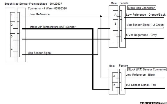
The MAP sensor or manifold absolute pressure sensor reads the pressure of the car engine's intake manifold and sends it to the ECU to adjust the fuel injection amount. In this powerful guide, we will discuss the 3 and 4 pin MAP sensor wiring diagram in less than 2 minutes.
Repairing electrical wiring, a lot more than any other household project is about protection. Install an outlet correctly and it's as safe as that can be; do the installation improperly and it can potentially deadly. That's why there are numerous guidelines surrounding electrical cabling and installations.
Print the wiring diagram off plus use highlighters to trace the signal. When you make use of your finger or perhaps the actual circuit with your eyes, it is easy to mistrace the circuit. 1 trick that We 2 to printing a similar wiring plan off twice.
Oldsmobile 3 8 Engine Diagram Map Sensor Diagram Base Website Map Sensor. 1996 Jeep Map Sensor Wiring Diagram. More. gm map sensor voltage chart.
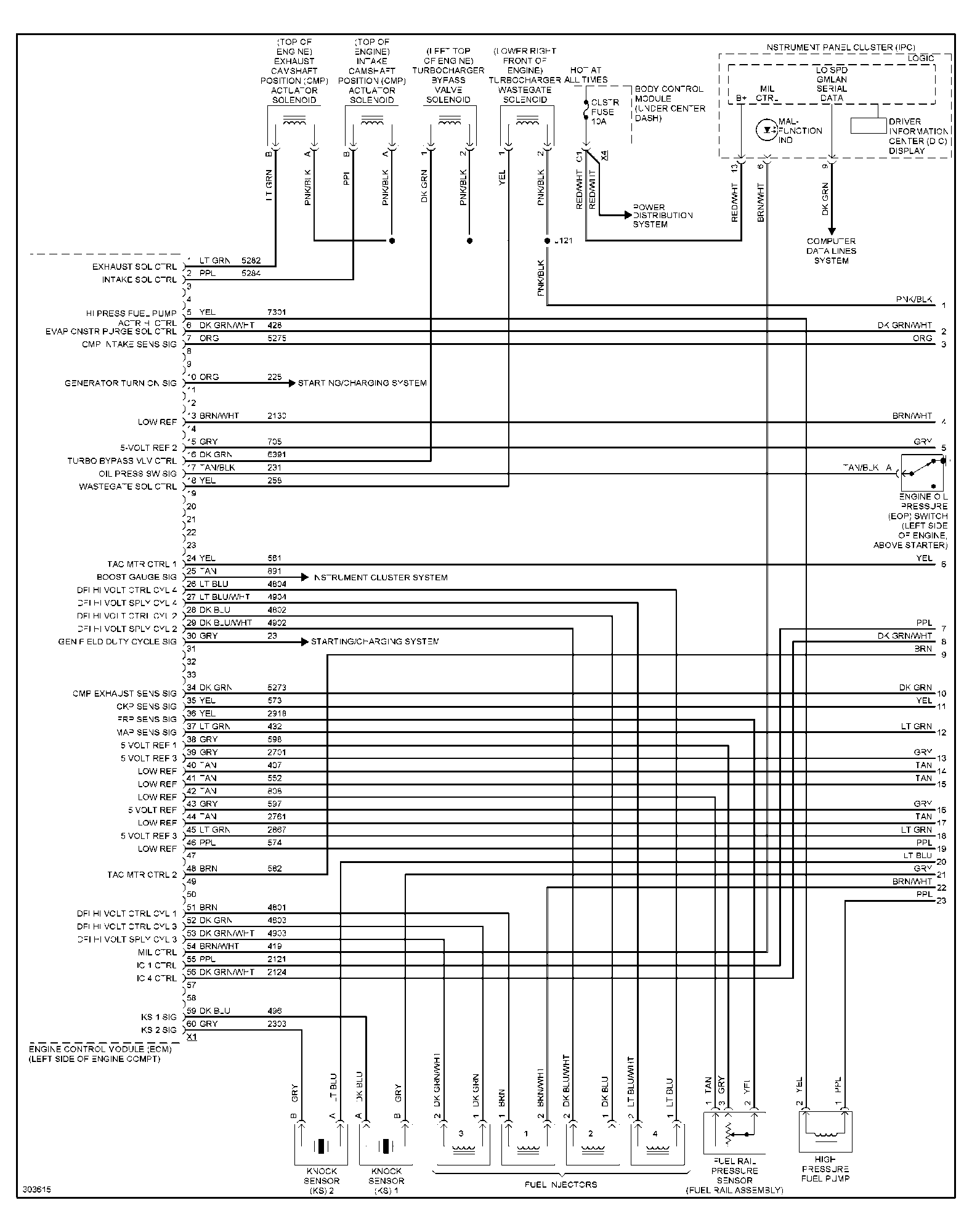
Gm Map Sensor Wiring Diagram wiring diagram is a simplified conventional pictorial representation of an electrical circuit. 10 1kz Engine Wiring Diagram Engine Diagram Wiringg Net Map Sensor Diagram Engineering.
The MAP sensor or manifold air pressure sensor is a main input to the ECM or engine control module. This sensor detect the intake manifold Presented using advanced software CG animation technology to help you understand. Part of our wiring diagram and electronic series shown here on this channel.
Map Sensor Wiring Diagram Source: i.pinimg.com. Read cabling diagrams from bad to positive in addition to redraw the signal as a straight line. All circuits are usually the same - voltage, ground, solitary component, and switches.
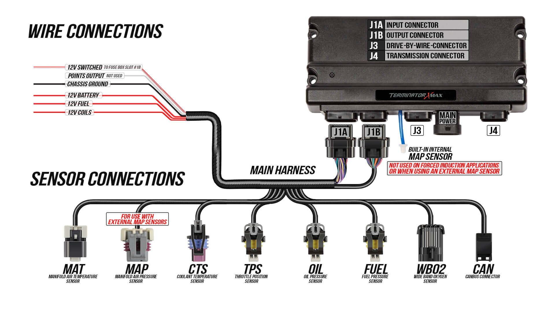
Map sensor wiring diagram. I have a new Dominator EFI system. Colors are the harness and numbers are location. MAP Sensor Wiring Diagram - YouTube. The various pressure sensors provide instant pressure data to the electronic control unit ECU of an engine.
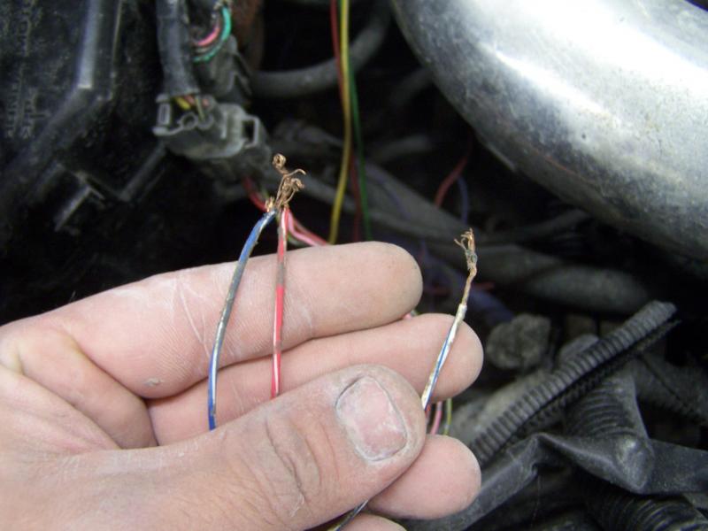
Issue Wiring In Gm Map Sensor For Lw Wiring Diagram 2011 Hyundai Sonata Map Sensor Connector Wiring Diagram For Map Sensor Fix Photo By Bjspencer85
Obd1 map sensor wiring diagram. Soarer wiring diagrams Wiring diagrams for your Toyota Soarer. Architectural wiring diagrams proceed the approximate locations and interconnections of receptacles lighting and enduring electrical services in a building.

Map Sensor Wiring Subaru Engines Exhausts And Modifications Subaru Owners Club Uk Subaru Forum For All Subaru Models
Issue Wiring In Gm Map Sensor For Lw. Wiring Diagram 2011 Hyundai Sonata Map Sensor Connector. 1993. Repair Guides. Iac Valve Wiring Diagrams. Wiring Diagram 2011 Hyundai Sonata Map Sensor Connector. Motiv 750 Port Injection W Aem Ems4 Progress Thread.
User manual | 3Bar Map Sensor Wiring Diagram. Twin Tec 3BarGuide Map Sensor Installation CAUTION: CAREFULLY READ INSTRUCTIONS Cable drive applications would install in the same fashion but will not have an IAT signal wire. Keep the vacuum line as short as possible and route...











Comments
Post a Comment