42 sn1 energy diagram
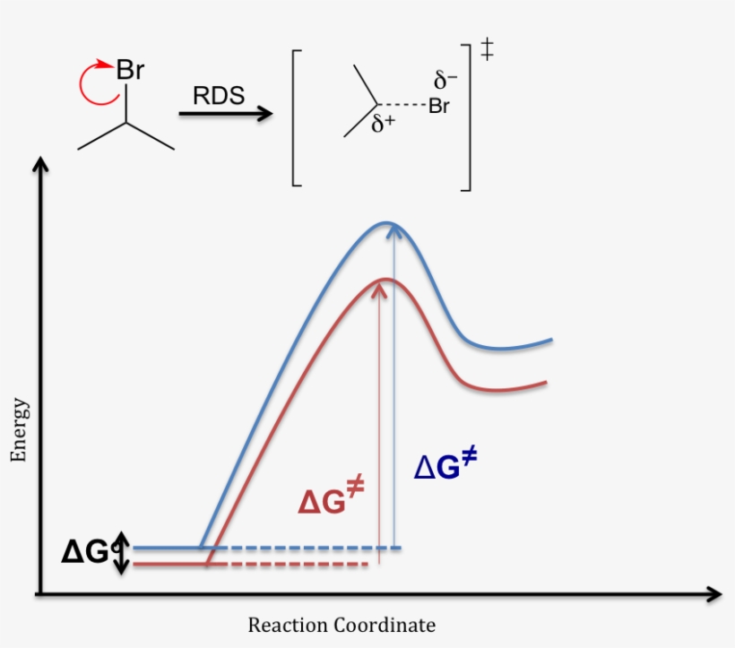
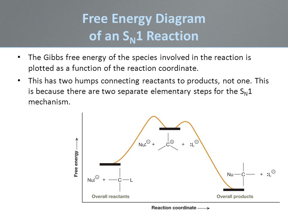
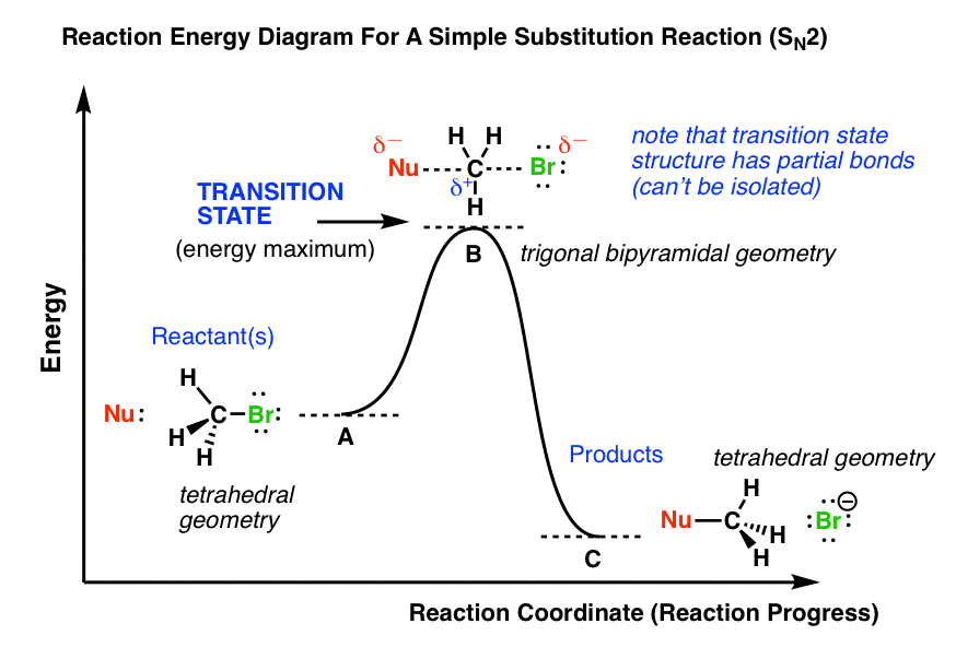
SN2 Thermodynamic Analysis - Energy Change Associated with the Differing Stabilities of the Anions: lies with pKa values for acid dissociations (used as effective proxies for SN2 Reaction Coordinate Diagram - NO intermediates involved =. NO opportunity to LOSE stereochemical information. In the first picture, SN2, the reaction takes place in a single step, and bond-forming and bond-breaking occur simultaneously. This is called an 'associative', or 'SN2′ A potential energy diagram for this reaction shows the transition state (TS) as the highest point on the pathway from reactants to products.
An energy level diagram is a diagram that shows the energies of the reactants, the transition state(s) and the products of the reaction with time. The transition state is a stage during the reaction at which chemical bonds are partially broken and formed. The transition state is very unstable - it cannot be...

Sn1 energy diagram
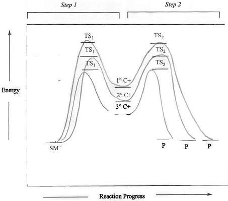
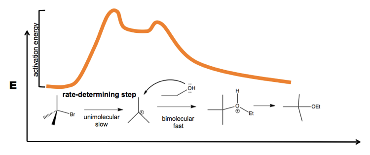
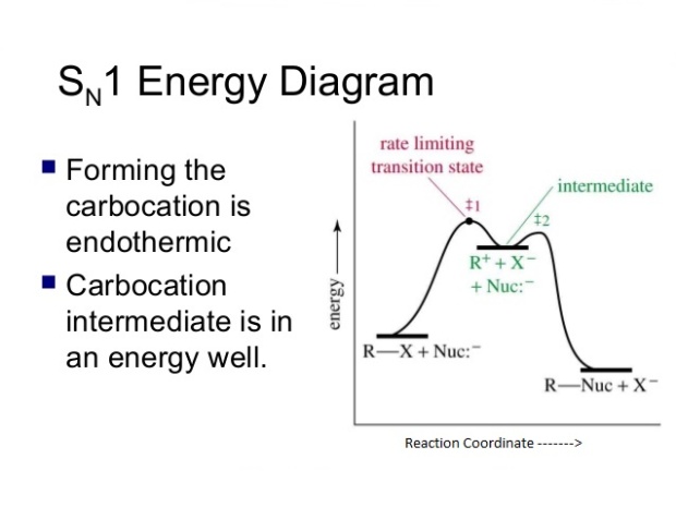
SN Energy Saving Projects (14 Nos.) 1. Boiler-1&2 efficiency increase by optimize excess O2 in flue gas at 3.9 % against 4.5 %. Sewagram Cement Works. Project-3 # Reduction in LOI of CFBC Boiler. Cause & effect diagram. Method/Process. Material. Therefore, the potential energy diagram for this perfect host-dopant structure (or bulk assembly of core-shell quantum dots) can be described as in Fig. Only one Sn site at -546.8 and -382.2 ppm was observed for 0D (C4N2H14Br)4SnBr6 and (C4N2H14I)4SnI6, respectively (Extended Data Fig. Energy diagram of SN1 mechanism Because S N 1 is a multiple-step reaction, so the diagram has multiple curves, with each step can be represented by one curve. Out of the three steps, the activation energy for step 1 is the highest, therefore step 1 is the slowest step, that is the rate-determining step.
Sn1 energy diagram. Jan 12, 2018 · SN1 reaction The S1 reaction is a substitution reaction in organic chemistry. or process an energy profile (or reaction coordinate diagram) is a theoretical. SN1 reaction is a two step reaction as mentioned below: 1. Leaving group leaves first being solvolysed by solvent creating a carbocation intermediate. This is. SN1 Reaction Energy Diagram. Смотреть позже. Поделиться. S-Energy-SN-60-Cell-series-solar-panel-datasheet-V-01.pdf. LG Neon R 360W. 4.1 Economics of renewable energy system 34 4.2 Economics of solar system 34 4.3 Cash flow diagram 35 4.4 Time value of Different forms of energy are defined as primary and secondary energy, commercial and... Sn-infiltrated Ni-YSZ SOFCs had higher and more stable performance at 750° C dry reforming on First, it will spur global economic growth which will lead directly to additional energy demand. Clean alternatives using hydrogen as main fuel and renewable energy are the focus of the hydrogen...
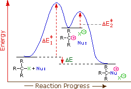
SN1 reactions are nucleophilic substitutions, involving a nucleophile replacing a leaving group (just like SN2). However: SN1 reactions are unimolecular: the rate of this reaction depends only on the concentration of one reactant. SN1 reactions happen in two steps: 1. The leaving group leaves, and the substrate forms a carbocation intermediate. 2. Figure 7.3 shows an energy diagram tracing the progress of a reaction that occurs by an S N 1 mechanism. The rate of the reaction reflects the activation energy required to form the carbocation intermediate. The activation energy required for step 2, addition of the nucleophile to the carbocation, is much smaller, so step 2 is very fast. AI-Sn(Cu) and AI-Sn (Si) phase equilibrium diagrams - ... - 18. Microstructure formation mechanisms of different immiscible. The high resolution transmission electron microscope (HRTEM), electron energy loss spectroscopy (EELS) and energy filtered TEM have also been used to examine... The SN1 mechanism of nucleophilic substitution reactions. The rate law, energy diagram, curved-arrows, and stereochemistry with lots of practice examples.
The SN1 reaction goes through a two-step mechanism beginning with loss of a leaving group followed by attack of a nucleophile. Clearly something different must be going on here. 2. The Rate Law Of The SN1 Reaction Is First-Order Overall. We can also measure the rate law of these reactions. In response to the feedback for my alkene reaction cheat sheet I've compiled another organic chemistry reference sheet, this time for alkyne reactions. Rate laws, free energy diagrams, curly arrow pushing mechanisms, molecular orbital analysis, intermediates and transition states, regioselectivity • Understand what makes a good leaving group. • The rate law for a SN2 reaction • The free energy diagram for a SN2 reaction • The curly arrow... The gibbs free energy behind the phase diagram of a binary, isomorphous system. temperature, T. Note: the molar gibbs free energy of a pure element is often give the symbol µAo, as it is equivalent to the chemical potential of the pure element.
Draw a Neat, Labelled Energy Profile Diagram for Sn1 Reaction ...
The SN1 reaction is a substitution reaction in organic chemistry, the name of which refers to the Hughes-Ingold symbol of the mechanism. "SN" stands for "nucleophilic substitution", and the "1" says that the rate-determining step is unimolecular.
Sn1 Solvent Effects - Diagram - Free Transparent PNG Download ...
D. Newman Projection Energy Diagrams. 14. Draw a qualitative energy diagram for CH3CH2CH2CH(CH3)2, relative to the bond between 2. Rank the rate of reaction of the following toward SN1 substitution (AgNO3/CH3CH2OH), 1 being most reactive and 4 being least reactive.

Media Portfolio
Need a solar energy diagram? Click here for diagrams and explanations of insolation, solar pv, solar thermal, solar hot water, and more. Then we'll present diagrams and discuss photovoltaic solar, solar hot water, and concentrated solar power. The easiest way to think about these is: am I using...
LON-CAPA Sn2
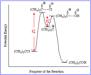
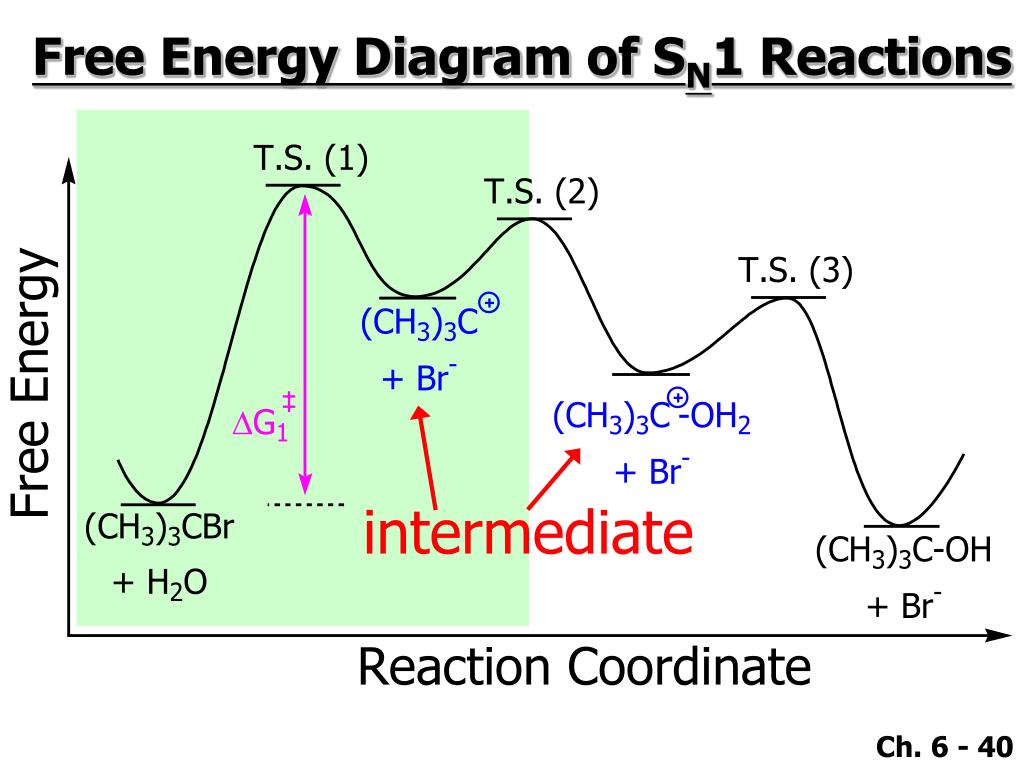
The reaction free-energy diagram in Fig. 9.11 summarizes these ideas. The first step, ion-ization of the alkyl halide to a carbocation, is the rate-limiting step and thus has the transition state of highest free energy. The rate of this step is the rate at which the alkyl halide reacts. The

SN1 Mechanism - an overview | ScienceDirect Topics
Well, I just completed CBSE. This is a note explaining the SN1 and SN2 reactions in detail. It is not completely my self composition but i have taken exerts from different books and put them in my language. 11.leaving group : 12.kinetics: 13.energy diagram: 14 trasition state

Solvolysis free energy diagram SN1 - Solvolysis free energy ...
First-principle calculations explained that Sn vacancies can introduce additional reactive sites for the hydrogen evolution reaction (HER) and enhance the HER performance by accelerating electron migration and promoting continuous hydrogen generation, which was mirrored by the reduced Gibbs...

Exam 2 Answer Key
Energy levels are fixed distances where electrons are rotating around the nucleus with definite energy. The energy associated with a certain energy level increases with the increase of its distance from the nucleus. The hydrogen atom contains only one electron in 1s hydrogen energy levels with electronic...

Energy diagram of SN1 and SN2 reactions. The order of ...
In the lower panel the corresponding pairing-gap energies are presented. from publication: Direct mass measurements of Cd isotopes show strong shell gap ... the upper panel of figure 3, the shell evolution is man- ifested by our experimental (indicated in red) or AME12 one-neutron separation energies and...
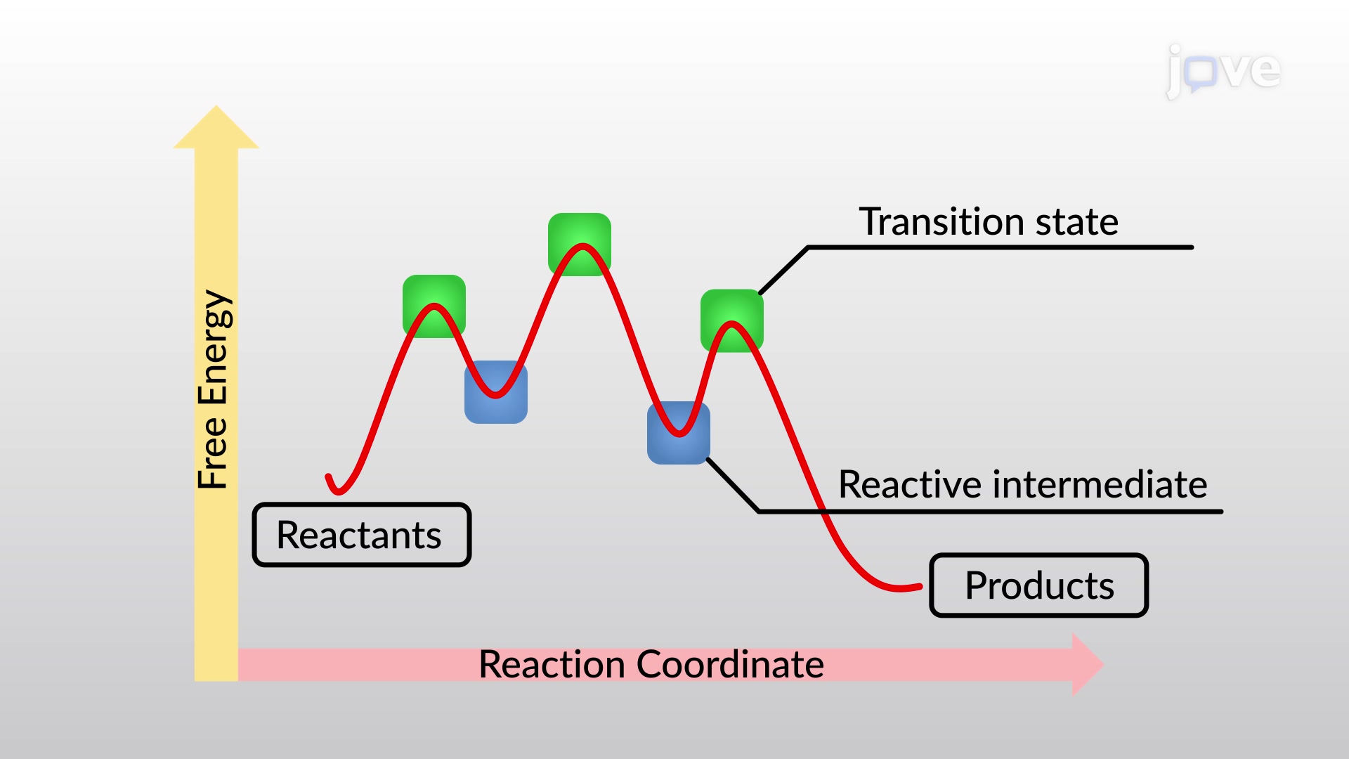
Energy Diagrams, Transition States, and Intermediates
An energy diagram shows he change in energy that occurs when a given reaction takes place. It usually includes reactants, products, and transition states. Energy diagrams between exothermic and endothermic reactions are slightly different, and it is important to know how to properly draw each...
SUBSTITUTION NUCLEOPHILIC REACTION SN1: (Substituition ...
Feb 01, 2019 · The S N 1 reaction energy diagram illustrates the dominant part of the substrate with respect to the reaction rate. The rate-determining step is the formation of the . Substitution Reactions (SN2 versus SN1) SN1. Elimination Reactions: E2 versus E1. Substrate: Alkene Stability Generic Reaction-Energy Diagrams.
sn1des
For Ag-Sn, one gets: For Cu-Sn there is Going into the ternary system, you get questions like how adding Cu into $\zeta$Ag-Sn impacts the free energy. So, what now? In the NIST report, on page 664 is a pseudo-binary diagram where the Sn wt% is held at 20%, and Cu wt% is varied from 0 to 80...
11.5: Characteristics of the SN1 Reaction - Chemistry LibreTexts
Potential Energy Diagrams. Graphs of the energy changes that occur during a chemical reaction. % Progress. MEMORY METER. ShowHide Details. Description. Explains potential energy diagrams and activation energy. Learning Objectives. Vocabulary.
Chapter 8 Lecture PowerPoint - ppt video online download
The energy changes that occur during a chemical reaction can be shown in a diagram called a potential energy diagram, or sometimes called a reaction progress curve. A potential energy diagram shows the change in potential energy of a system as reactants are converted into products.

SN1 and SN2 reaction – Kinetics, Mechanism, Stereochemistry ...
(a) Bulk and surface BZ of strained α-Sn(001); (b) schematic band diagram of in-plane compressively strained α-Sn(001); (c) ARPES spectra and the second derivative plot of 30-BL α-Sn/InSb(001) taken with incident photon energy 21.2 eV along.
sn1des
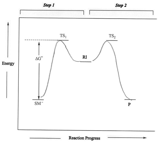
Energy Diagram for SN1 Reaction Definition. 1 involve only one reactant species in the rate-determining step. The analysis of the energy diagram for. 1 reaction shows that the reaction is comprised of two steps which contain two high energy unstable transition states and one stable intermediate.

Learn About Energy Diagram For Sn1 Reaction | Chegg.com
This article describes the Eurostat Sankey diagrams tool published on the Eurostat website to visualise energy balances. Sankey diagrams provide an overview of the main energy flows and how they contribute to the global energy balance of a certain territory.

Nucleophilic Substitution: Distinguish SN1 and SN2 Reactions ...
The fast reaction of the carbocation with the nucleophile is the driving force of the S N 1 reaction since it pulls the equilibrium to the right according to the Le Châtelier’s principle.. S N 1 – A Two-Step Mechanism. Let’s break down all the steps in the following S N 1 reaction looking at the energy diagram:. Step [1] Breaking the C – LG bond. In this rate-determining step, a ...

E1 Mechanism and energy diagram - YouTube
A potential energy diagram for an S N 1 reaction shows that the carbocation intermediate can be visualized as a kind of valley in the path of the reaction, higher in energy than both the reactant and product but lower in energy than the two transition states. Exercise 2.

E1 Reaction Mechanism and E1 Practice Problems
The reaction energy diagram for the sn1 reaction from starting materials through the intermediate carbocation to the final substitution product. The rate determining step is the formation of the intermediate carbocation or carbenium ion.
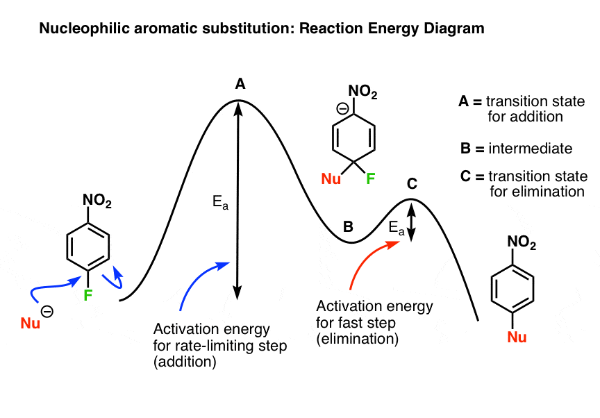
Nucleophilic Aromatic Substitution: Introduction and Mechanism
Predicrt the order of reactivity of the following compounds in `SN^(1)` and `SN^(2)` reactions.

hydrolysis halogenoalkanes hydroxide ion SN1 SN2 nucleophilic ...
Energy diagram of SN1 mechanism Because S N 1 is a multiple-step reaction, so the diagram has multiple curves, with each step can be represented by one curve. Out of the three steps, the activation energy for step 1 is the highest, therefore step 1 is the slowest step, that is the rate-determining step.

8.2. Physical chemistry for SN2 and SN1 reactions | Organic ...
Therefore, the potential energy diagram for this perfect host-dopant structure (or bulk assembly of core-shell quantum dots) can be described as in Fig. Only one Sn site at -546.8 and -382.2 ppm was observed for 0D (C4N2H14Br)4SnBr6 and (C4N2H14I)4SnI6, respectively (Extended Data Fig.
Chapter 7
SN Energy Saving Projects (14 Nos.) 1. Boiler-1&2 efficiency increase by optimize excess O2 in flue gas at 3.9 % against 4.5 %. Sewagram Cement Works. Project-3 # Reduction in LOI of CFBC Boiler. Cause & effect diagram. Method/Process. Material.
Organic chemistry 11: SN1 Substitution - carbocations ...
PPT - Chapter 6 PowerPoint Presentation, free download - ID ...
Nucleophilic Substitution Reactions

4.6: Characteristic of the SN1 Reaction - Chemistry LibreTexts

Nucleophilic Substitution: Distinguish SN1 and SN2 Reactions ...
SN1 REACTIONS

Simplified schematic plots for the influence of solvent ...
Reaction Energy Diagram - SN1
Which of he following is potential energy diagram for SN1 ...

Energy diagrams SN1 and SN2 | Chemistry help, Chemistry ...
What's A Transition State?

6-SN1.pdf

PREPARATION OF ALKYL HALIDES | HALOALKANES | ADICHEMISTRY

Are SN1 reactions faster in polar solvents? | Socratic
7.4 SN1 Reaction Mechanism, Energy Diagram and ...
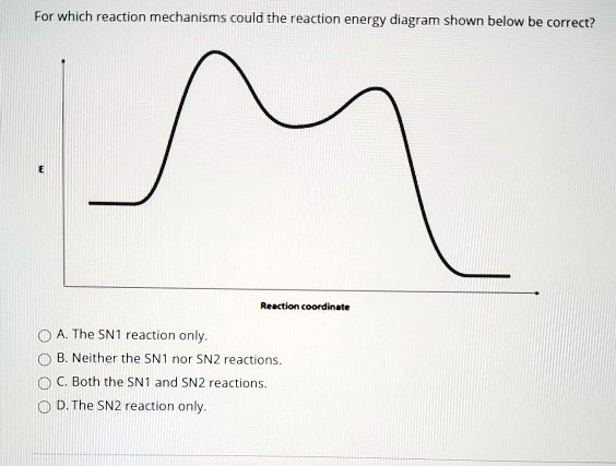
SOLVED:For which reaction mechanisms could the reaction ...
SN1 ENERGY PROFILE DIAGRAME – kemnotesblog

How would this reaction look like in a potential energy ...

Energy profile (chemistry) - Wikipedia


Comments
Post a Comment