43 ladder diagram symbols
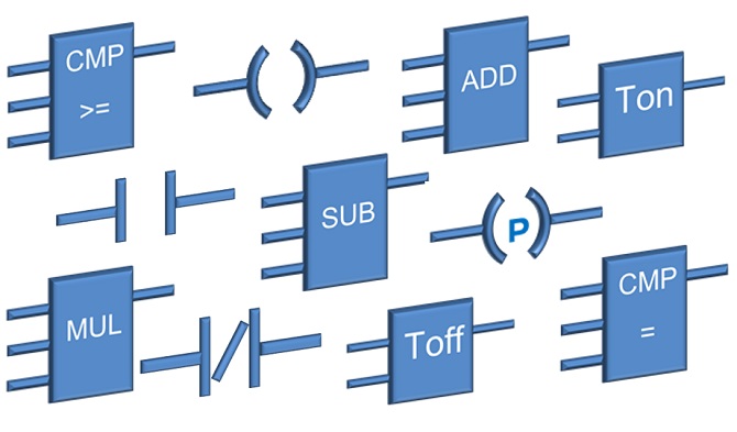
The name " ladder diagram " is derived from the program's resemblance to a ladder with two vertical rails and a series of horizontal rungs between them. The rails are called "power rails" in the ladder diagram. Fig. 9.3 illustrates a typical ladder diagram and its conventions. Figure 9.3. To continue with my last tutorials about Ladder Logic Symbols - PLC Ladder Diagram Symbols lets talk about few more interesting instruction which commonly being used and very useful in PLC Programming. In last tutorial we have seen and understand bit logic instructions. Today we are going to learn computational mathematical instructions (Integer Math) which is widely used to get certain ...
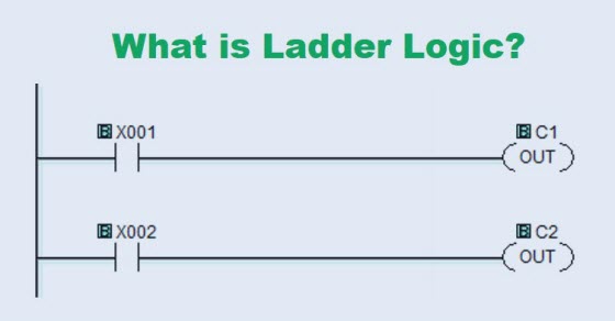
Ladder logic looks almost identical to a ladder diagram except the contacts and coils are replaced with computer bits. But we still need to illustrate what these bits represent, so we use logic symbols. These symbols come straight from relay logic diagrams even if some of the components are digital now.

Ladder diagram symbols
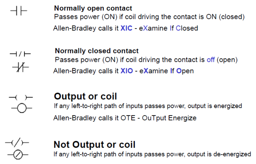
Electrical Ladder Drawing Basics. Feb. 1, 2006. Understanding the basic layout, symbols, and cross-reference system of ladder diagrams will help you become a better troubleshooter. Roger Zieg. The five most used ladder logic symbols are as follows: Normally Open Contact, Normally Closed Contact, Output Energize, Output Latch and Output Unlatch. These five instructions are commonly used in ladder logic for bit manipulation. The first two are conditional instructions that will allow the current to flow depending on the status of the bit. plc ladder diagram symbols Ladder Logic Symbols - Operation and Common Uses The ladder logic symbols that are used in PLC programming have been derived from traditional relay logic control circuits. If you have a basic knowledge of electric circuits then getting started in ladder logic programming should be a breeze.
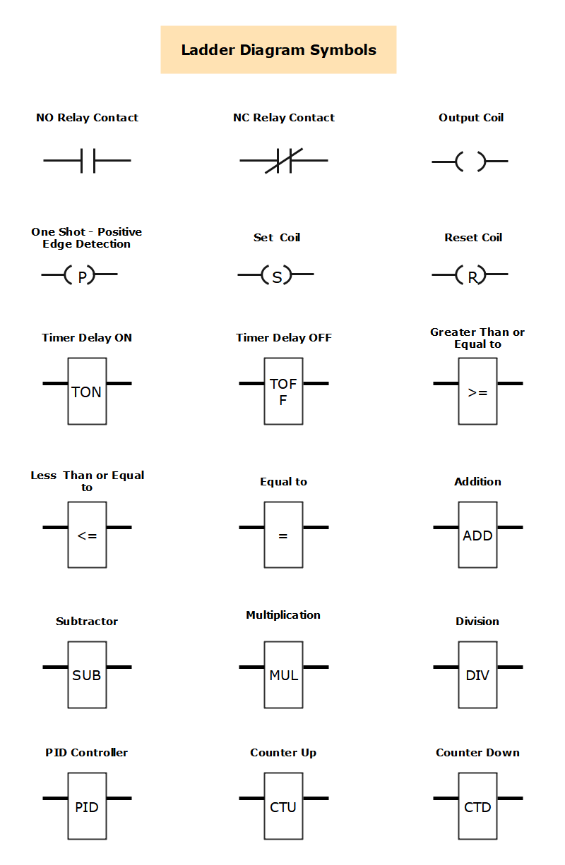
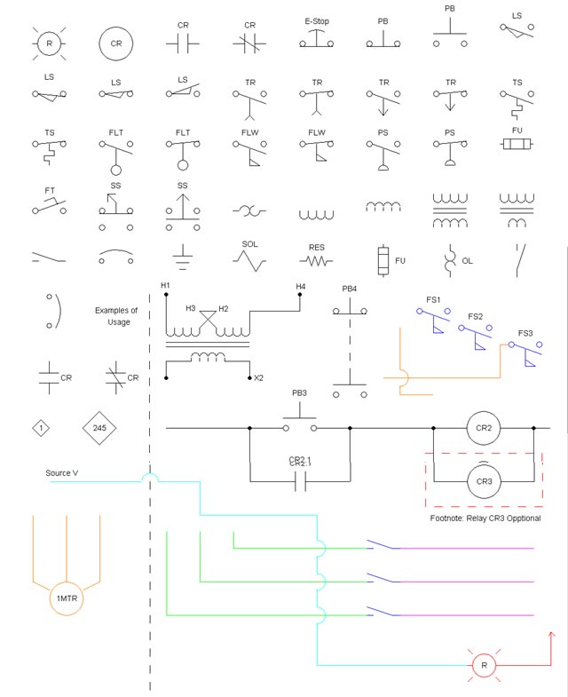
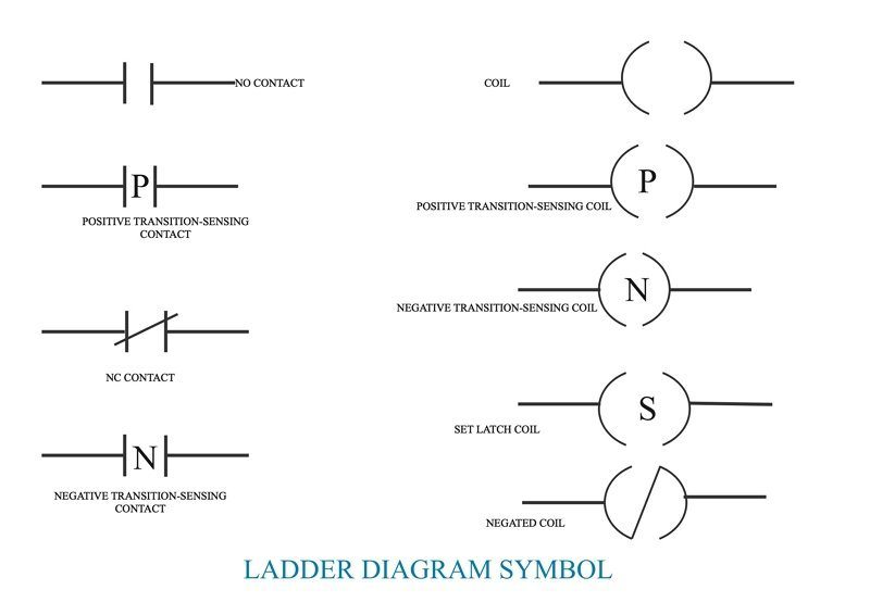
Ladder diagram symbols. Ladder Diagram Symbols. Here are a number of highest rated Ladder Diagram Symbols pictures on internet. We identified it from reliable source. Its submitted by doling out in the best field. We say yes this nice of Ladder Diagram Symbols graphic could possibly be the most trending topic similar to we portion it in google pro or facebook. Ladder Diagram Symbols are the building blocks of ladder diagrams and they are also called ladder logic symbols. Every Ladder Symbol represents a certain ladder instruction. We use these symbols in the PLC programming that have been derived from relay logic control circuits. Check the common-used ladder diagram symbols below. common is the ladder diagram, so called because it looks like the symbols that are used to represent the components in the system have been placed on the rungs of a ladder. From this point forward, ladder dia-grams will be referred to as "schematic" diagrams, or simply "schematics." A typical schematic of a pack- These graphic symbols are the ones used most often on ladder diagrams for fluid power electrical control circuits. They are standard JIC (Joint Industrial Council) symbols as approved and adopted by the NMTBA (National Machine Tool Builders Association). They have been extracted from the Appendix of the NMTBA Specification EGPl-1967.
Ladder Logic Symbols. Here are a number of highest rated Ladder Logic Symbols pictures upon internet. We identified it from reliable source. Its submitted by executive in the best field. We give a positive response this kind of Ladder Logic Symbols graphic could possibly be the most trending subject with we share it in google lead or facebook. Ladder logic (also known as ladder diagram or LD) is a programming language used to program a PLC (Programmable Logic Controller). It is a graphical PLC programming language which expresses logic operations with symbolic notation. Ladder logic is made out of rungs of logic, forming what looks like a ladder - hence the name 'Ladder Logic'. Oct 2, 2018 - Ladder logic symbols are a set of symbols used in PLC ladder diagrams. Download all the IEC 61131-3 ladder diagram symbols as DWG, PDF and PNG files here. Ladder Logic Diagram Example 1 Computer Aided Manufacturing TECH 4/53350 27 Task: Draw a ladder diagram that will cause the output, pilot light PL2, to be on when selector switch SS2 is closed, push button PB4 is closed and limit switch LS3 is open. (Note: no I/O addresses yet.) Thought Process
PLC ladder diagram symbols.docx - PLC ladder diagram symbols. School Technological Institute of the Philippines. Course Title ECE MISC. Uploaded By GeneralScorpion5297. Pages 3. This preview shows page 1 - 3 out of 3 pages. View full document. PLC ladder diagram symbols. Basic Electrical Ladder Diagrams. Amarante Pruvost. September 25, 2021. Types Of Electrical Drawing And Diagrams Electrical Technology Electrical Diagram Electricity Electrical Symbols. Plc Program For Forward And Reverse Motor Control Ladder Logic Electrical Circuit Diagram Electronic Schematics. Ladder logic symbols are the fundamental programming components used in ladder diagrams. In PLC programming, ladder logic symbols can be used individually or in combination to create logic instructions. Ladder Diagram symbols 12 TM240 - Ladder Diagram (LD) Negative edges Relationship between the input signal and result Negative edge This contact is used to detect a negative edge of a signal. If the value of a variable is switched from TRUE to FALSE, the result becomes TRUE for one cycle.
JIC Standard Symbols for Electrical Ladder Diagrams - Womack ...
Ladder logic symbols are the basic building blocks for ladder diagrams. Right here you will find all the ladder diagram symbols which are described in IEC 61131-3. The symbols are available for download in all formats and in a PDF-file. It's absolutely crucial to know about the symbols when you are working with ladder logic.
PLC Ladder Logic Symbols - PLC - Engineers Community
In drawing a ladder diagram, certain seven conventions are adopted: Convention 1 // The vertical lines of the diagram represent the power rails between which circuits are connected. The power flow is taken to be from the left-hand vertical across a rung. Convention 2 // Each rung on the ladder defines one operation in the control process.
Ladder Logic Symbols - Ladder Logic World
Ladder Diagram A ladder diagram, shown in figure 3, is a diagram that explains the logic of the electrical circuit or system using standard NEMA or IEC symbols. A ladder diagram is used to point out relationships between circuit components, not the actual location of the components.

Electromechanical Relay Logic Worksheet - Digital Circuits
In last tutorial we have seen computational mathematical instructions Ladder Logic Symbols(PLC Ladder Diagram Symbols-II.This tutorial we will continue with "Timers" and "Counters" instructions.Timers are important part of PLC without which it is very difficult to think of executing a process.Timers are blocks that count the time as specified by the user and the executes the algorithm ...

Ladder Logic Symbols - All PLC Diagram Symbols
Ladder logic looks almost identical to a ladder diagram except the contacts and coils are replaced with computer bits. But we still need to illustrate what these bits represent, so we use logic symbols. These symbols come straight from relay logic diagrams even if some of the components are digital now.
Ladder Logic 201: Inputs - AutomationPrimer
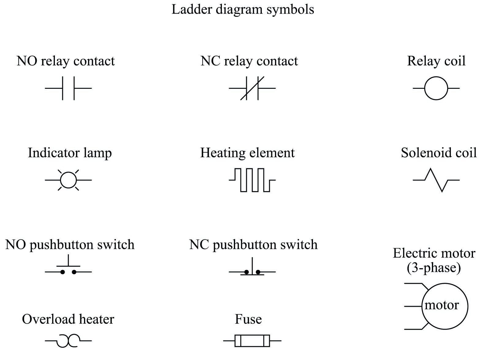
The graphic symbols in the ladder diagram are the simplification and abstraction of the graphic symbols in the relay contact control diagram. The corresponding relationship between the two is shown in the table. Table comparison between graphic symbols in ladder diagram and relay contact control diagram
Engineer On A Disk
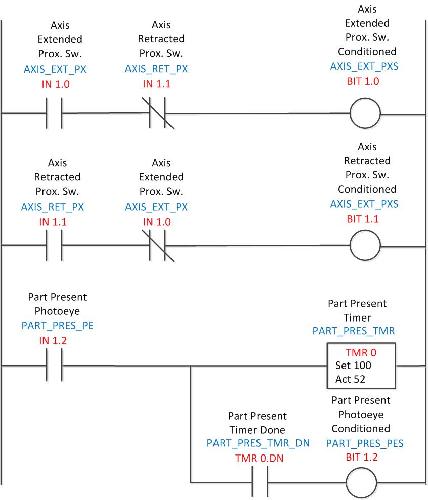
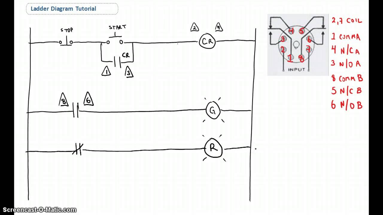
A complete PLC ladder diagram program then consists of several rungs, each controlling an output interface which is connected to an output field device as shown in the below Figure. Ladder Diagrams Each rung is a combination of input conditions (symbols) connected from left to right between two vertical lines, with the symbol that represents ...

The Basics of Ladder Diagrams for Programming PLCs
A line (ladder) diagram is a diagram that shows the logic of an electrical circuit or system using standard symbols. A line diagram is used to show the relationship between circuits and their components but not the actual location of the components. Line diagrams provide a fast, easy understanding of the connections and use of components.

Ladder Logic Symbols | PLC Programming in RSLogix 5000 Studio ...
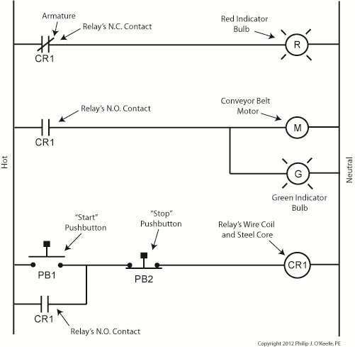
In ladder diagrams, the load device (lamp, relay coil, solenoid coil, etc.) is almost always drawn at the right-hand side of the rung. While it doesn't matter electrically where the relay coil is located within the rung, it does matter which end of the ladder's power supply is grounded, for reliable operation. Take for instance this circuit:
Ladder Diagram Symbols and Meanings | EdrawMax Online
The example below shows a ladder diagram with pushbuttons (PB), control relays (CR), a motor (M) and a light (L). Similarities with Ladder Diagrams Ladder logic was designed to have the same look and feel as electrical ladder diagrams, but with ladder logic, the physical contacts and coils are replaced with memory bits. Let's take a look.

Relays in Ladder Logic Tutorials | Instrumentation Tools
ladder diagram symbols_text.pdf download. download 6 files . SINGLE PAGE PROCESSED JP2 ZIP . Uplevel BACK 952.6K . ladder diagram definition_jp2.zip download. 1.2M . ladder diagram examples_jp2.zip download. 777.2K ...
Ladder Logic Tutorial with Ladder Logic Symbols & Diagrams
plc ladder diagram symbols Ladder Logic Symbols - Operation and Common Uses The ladder logic symbols that are used in PLC programming have been derived from traditional relay logic control circuits. If you have a basic knowledge of electric circuits then getting started in ladder logic programming should be a breeze.

PLC Ladder Logic Diagram Symbols-III – microdigisoft.com
The five most used ladder logic symbols are as follows: Normally Open Contact, Normally Closed Contact, Output Energize, Output Latch and Output Unlatch. These five instructions are commonly used in ladder logic for bit manipulation. The first two are conditional instructions that will allow the current to flow depending on the status of the bit.

Ladder Diagram (LD) Programming | Basics of Programmable ...
Electrical Ladder Drawing Basics. Feb. 1, 2006. Understanding the basic layout, symbols, and cross-reference system of ladder diagrams will help you become a better troubleshooter. Roger Zieg.

Ladder Logic Symbols - All PLC Diagram Symbols
Engineer On A Disk

Explanation of Mitsubishi PLC ladder diagram symbols ...

LADDER Logic basic for Beginners - plc4me.com

Ladder logic - Wikipedia

Ladder Logic Symbols | PLC Programming in RSLogix 5000 Studio ...

PLC Ladder Logic Diagram Symbols-II – microdigisoft.com

Electro-Magnetic World: Basic Ladder Logic Symbols
Ladder Diagram Symbols and Meanings | EdrawMax Online

Engineering Fundaz: PLC Ladder Diagram Basics

circuit diagram: Drawing Software Building Wire Diagrams ...
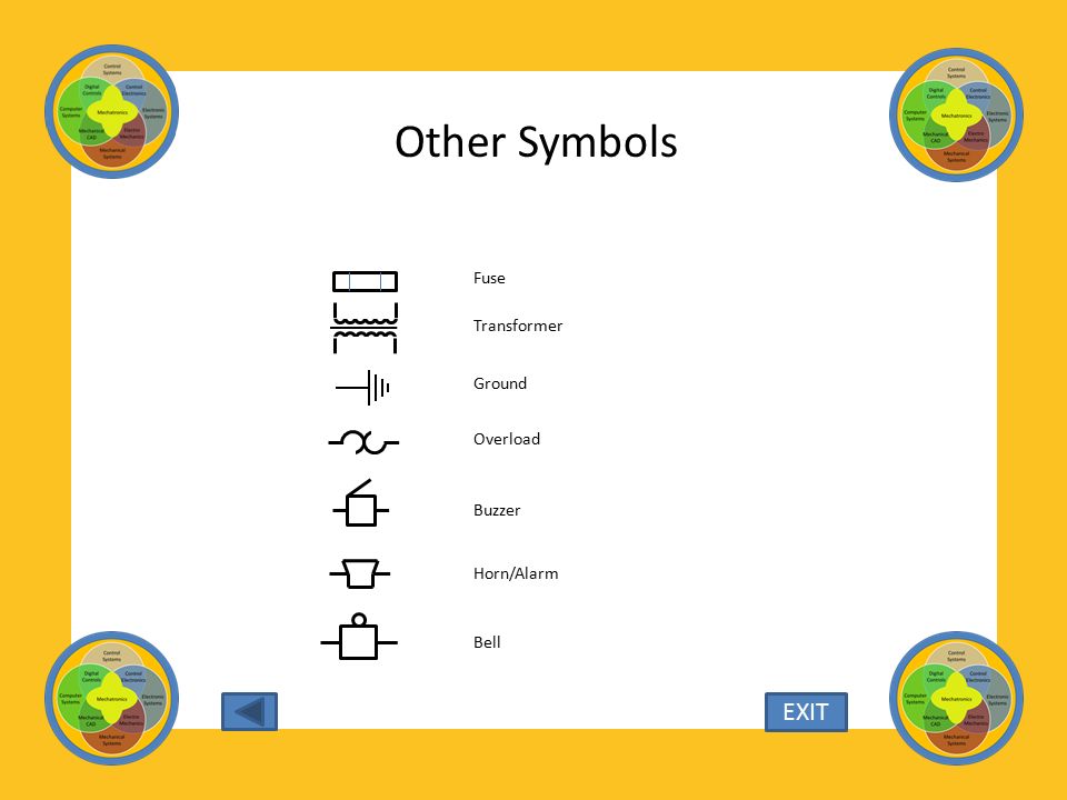
Ladder Diagram Symbols. Study the various symbols identified ...

Session 05 - Ladder Logic Introduction

Ladder logic symbols Function... - Graduate from Kurinjipadi ...
Ladder Diagram | Engineering Expert Witness Blog

Ladder Diagram - an overview | ScienceDirect Topics

Electronic symbol - Wikipedia

Ladder†Diagrams | Ladder Logic | Electronics Textbook
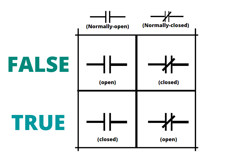
The Binary Concept Applied to Ladder Logic (I) - Binary Code
Electrical Schematic Software (Ladder Logic)
What Is Ladder Diagram | EdrawMax Online

PLC Ladder Rung Symbols | Ladder logic, Ladder, Electronic ...

5: Ladder Logic | Dr. Stienecker's Site

JIC Standard Symbols for Electrical Ladder Diagrams - Womack ...
Equivalent Logic Gates using PLC Ladder Diagrams | PLC ...
Ladder Diagram Basics #1 | Diagram, Ladder logic, Electrical ...
Relay Circuits and Ladder Diagrams | Relay Control Systems ...
Ladder Diagram | Schematic Diagram | Wiring Diagram ...

File:برنامه نویسی نردبانی.gif - Wikimedia Commons


Comments
Post a Comment