42 diagram of a well
WELL SEAL (Section K) Used in above-ground installations to provide a positive seal inside casing. CHECK VALVE (Section G) On pump installations, a Check Valve installed near the tank inlet holds water in the tank when the pump is idle. TANK TEE ... Well Diagram 2012.indd Nitrate Filter Diagrams. Phosphate Systems. Reverse Osmosis. Sediment Filters. Soda Ash Systems. Tannin Filters. Ultraviolet Sterilizer Systems. Ultra-Filtration Systems. Well & Storage Tanks.
The diagram of ear is important from Class 10 and 12 perspective and is usually asked in the examinations. A brief description of the human ear along with a well-labelled diagram is given below for reference. Well-Labelled Diagram of Ear. The External ear or the outer ear consists of: Pinna/auricle is the outermost section of the ear.

Diagram of a well
Well Diagram. This illustration is intended to represent some of the components that can be included in a water well system and is not intended as an installation guide. Check local or state codes for actual requirements and restrictions. All external entities are shown on the context diagram as well as major data flow to and from them. The diagram does not contain any data storage. The single process in the context-level diagram, representing the entire system, can be exploded to include the major processes of the system in the next level diagram, which is termed as diagram 0. Well and Water System Diagram. Move your mouse over a county name to view the contact number. (1) Check Valve Located at the top of the pump to hold water in the tank and prevent backflow through the pump. (2) Rope Insert Adapter A male or female pipe adapter with a loop for attaching a pump safety rope or cable. Constructed of stainless steel ...
Diagram of a well. Here are some of the more important elements included in the water well diagram above. Borehole - The borehole should be about 50mm (2 inches) wider all around than the well casing.The borehole needs to be clear of obstructions all the way down, and should be deep enough to reach the lowest expected water level. 220v 3 wire well pump wiring diagram. Red and yellow might indicate that it is a 2 wire 220 volt pump. 2 wire well pump diagrams are slightly easier to understand and are more straight forward to wire. Electrical ac dc 3 wire 240v for well pump i have a 220v water well pump submersible this is for farm use. Splice the wire to the motor leads. Download now free wellbore schematic excel template which contain drawings and tally templates for almost all tools required for drilling, completion & workover operations. This file is very awesome and helpful to produce high quality representative drawings for almost all tools during the life cycle of the well. Diagrams --Typical Pump Installations. The information provided here is for educational purposes only. Technically qualified personnel should install pumps and motors. We recommend that a licensed contractor install all new systems and replace existing pumps and motors. Failure to install in compliance with local and national codes and ...
Well Diagram. The quality water system products described here and illustrated on the front page are some of the Baker Water Systems products used in a typical well system. (The section in the catalog where these items can be found is located in parentheses) This list and the illustration on the front page are not intended as an installation guide. Human Body Diagram. The human body is one complex network, universally accepted as the most intriguing construct. It is certainly the most widely studied structure the world over. Undermentioned are little- and well-known facts about the human body. The well labelled diagram of an animal cell consists of all the organelles and the structural components of an animal cell. An animal cell is the basic unit of any living animal. All the cells found in any living animal are made up of similar components and organelles and are eukaryotic cells. Hence, a well labelled diagram of animal cells will be quite uniform amongst all the different ... Diagram. Wellness. Infographics: Single Stage Deepwell Cargo Pump. Deepwell cargo pumps are electrically driven cargo discharge pumps which are now used in place of Cargo Operated Pump Turbine (COPT) on tanker ships. Learn about the different parts of the pump in this infographics. pongawn.
ConceptDraw is Professional business process mapping software for making process flow diagram, workflow diagram, general flowcharts and technical illustrations for business documents. It is includes rich examples, templates, process flowchart symbols. ConceptDraw flowchart maker allows you to easier create a process flowchart. Use a variety of drawing tools, smart connectors, flowchart symbols ... Well Diagram. The quality water system products described here and illustrated are some of the Baker Water Systems products used in a typical well system. This list and the illustration are not intended as an installation guide. Check local codes for actual requirements and restrictions. (Scroll over Numbered part for Detailed View) The pumping unit is placed inside the well casing and connected to a power source on the surface. The Water Systems Council had a more detailed well component diagram and other well-owner education materials. 2. Well component descriptions adapted from the National Ground Water Association (2017) Replace a Two Wire Pump. The diagrams for both the two and three wire pumps can be downloaded using Adobe. To replace the two wire pump: After determining the voltage is zero, disconnect the motor wires directly from the pressure switch box, M1 and M2. The green ground wire should also be terminated to the box and a ground coming from the panel.

Well Construction
Monitoring Well / Piezometer Completion Diagram Flush Mount Project Name Project Number Northing Project Location Start Date / Time Easting Well / Piezometer ID End Date / Time Ground Surface Elevation Static Water Level (ft btoc) Top of Casing Elevation Measured On Concrete Pad Filter Pack Type

Drilling Well Diagram Images Stock Photos Vectors Shutterstock
The diagrams reflect two different levels of detail. Please remember that the scope of work is critical in regards to the amount detail required for the different Diagrams. The first type of site security is shown on diagram number 1. In this scenario, the well pad size, well heads, facilities and containment volumes and more attributes are listed.
1
This Livewell or Bait Well setup is easy to install. As you can see by the diagram the overflow outlets directly through the hull of the boat above the water line allowing you to refresh and recirculate the water in your livewell or bait well tank. This design is best if you are doing a horizontal mount livewell.

Oil Well Diagram Images Stock Photos Vectors Shutterstock
857 oil well diagram stock photos, vectors, and illustrations are available royalty-free. See oil well diagram stock video clips. of 9. ground pump drilling well diagram layer of soil underground cross-section of earth reservoir oil and gas oil rig underground well diagram drill 3d pipeline underground oil well drilling illustration. Try these ...
How To Install And Wire A Well Pump Well Pump Installation Guide
Well Shadow is an application designed to make creating wellbore diagrams and well histories quick and easy. It is no longer necessary to use Microsoft Excel to create cumbersome wellbore diagrams. Well Shadow was developed from the ground up, by a petroleum engineer for petroleum engineers, specifically for the purpose of efficient wellbore ...

Anatomy Of A Well Terms Rps Solar Pumps America S 1 Solar Well Pumps
Multiple Diagram Versions and Duplication Feature. Retain Wellbore Diagram History: An unlimited number of diagrams can be created for each well allowing users to retain a fully documented history of each phase of the well's life; from initial completion to recompletion or a major workover, each version captures a snapshot of what the well looked like at the time.
5 Constructing Casing And Covering The Well Ontario Ca
well schematic diagrams for interceptor wells . phelps dodge sierrita mine, pima county, arizona . errol l. montgomery & associates, inc. appendix a . contents figure . a-1 schematic diagram of well construction for interceptor well iw-1 .

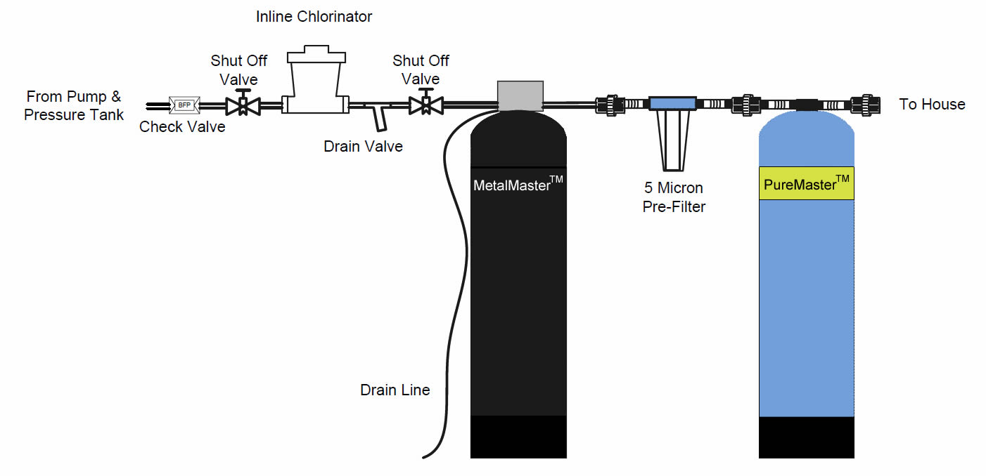
Water Treatment Service Insallation
Download scientific diagram | Schematic diagram of typical well design, showing (A): structure of an exploration well; and (B): a production well. Depths to which different casings are used vary ...

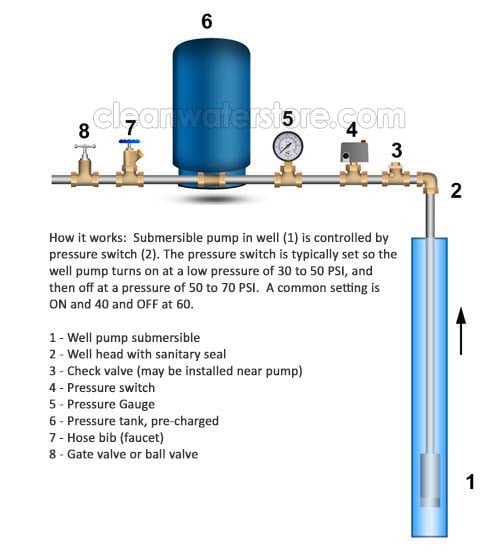
Clean Well Water Report Well Pump Pressure Tank Diagram
Water Pump Wiring Troubleshooting Repair Diagrams. Well pump installation guide water wiring troubleshooting install a submersible 6 lessons 4 hp 2 wire motor 10 diagrams three 110volt electrical 120v rs485 hydrostatic cesspool deep sea shurflo 9300 9325 083 single phase starter 3 vs directly to generator wires cut countyline 1 gpm series 110 v terry love using relays flotec model fp3212 02 ...
Baker Water Systems Well Diagram
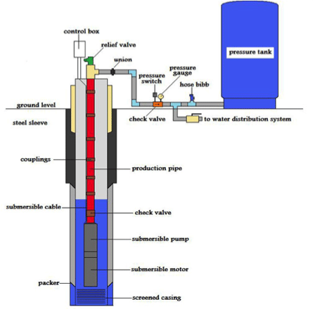
Well Pump & Pressure Tank Diagram PRESSURE TANK FROST LINE CASING Above Ground Installation 1 2 4 5 6 8 7 9 10 11 12 13 15 16 14 PUMP 3 1. Check Valve Located at the ...

Conventional Pump Pressure Tank Installation Diagram Pitless Adapte Hhpac
Pump drain. Diagram not to scale,. Pump intake. ProLong live. Ranger Boat Live Well Diagram, Live Well Pump Installation, Recirculating Live Well Diagrams, One Live Well Pump Plumbing Diagrams, Boat.Jan 12, · Well Zooker, not looking at it The drain out the bottom has a cap to twist off it and there is a over flow for for it.

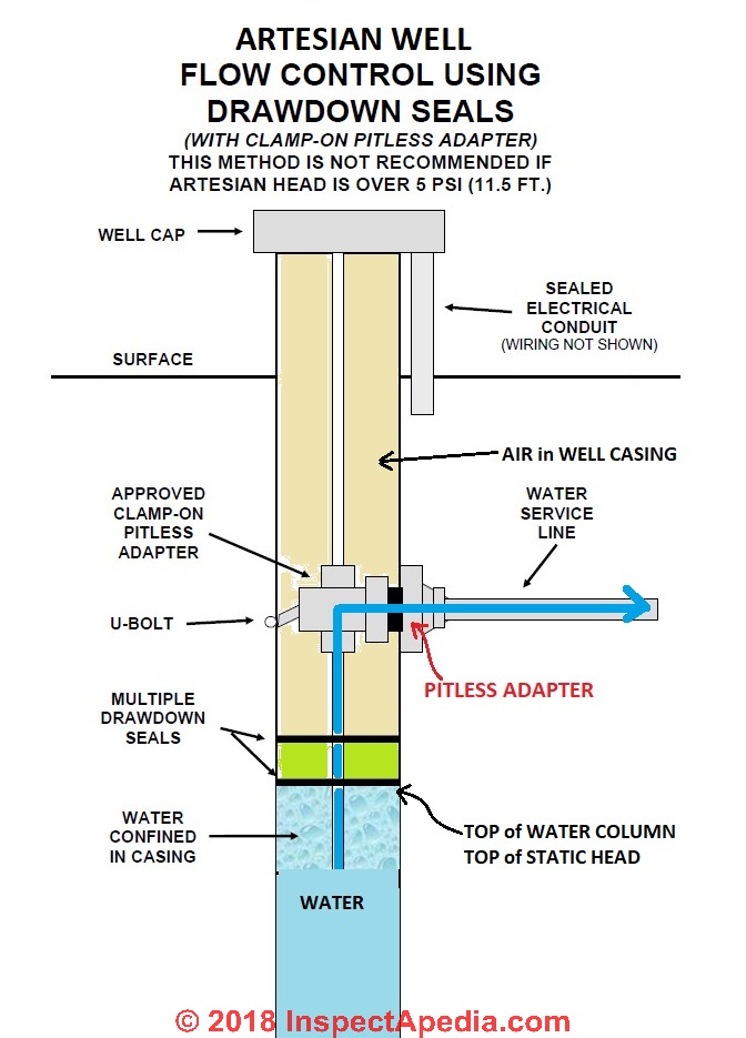
Artesian Water And Artesian Wells
Well and Water System Diagram. Move your mouse over a county name to view the contact number. (1) Check Valve Located at the top of the pump to hold water in the tank and prevent backflow through the pump. (2) Rope Insert Adapter A male or female pipe adapter with a loop for attaching a pump safety rope or cable. Constructed of stainless steel ...
Wells Keystone Clean Water Team Ccgg
All external entities are shown on the context diagram as well as major data flow to and from them. The diagram does not contain any data storage. The single process in the context-level diagram, representing the entire system, can be exploded to include the major processes of the system in the next level diagram, which is termed as diagram 0.
Well Water System 3 Diagram
Well Diagram. This illustration is intended to represent some of the components that can be included in a water well system and is not intended as an installation guide. Check local or state codes for actual requirements and restrictions.

Labeled Well Pump Diagram Strikecheck Strikecheck

Water Wells In Floodplains What You Need To Know

New Jersey Well Drilling Diagram

Baker Water Systems Well Diagram Water Well Water Treatment System Home Water Filtration

Typ 2 Wire Gif 593 528 Submersible Well Pump Well Pump Well Pump Repair

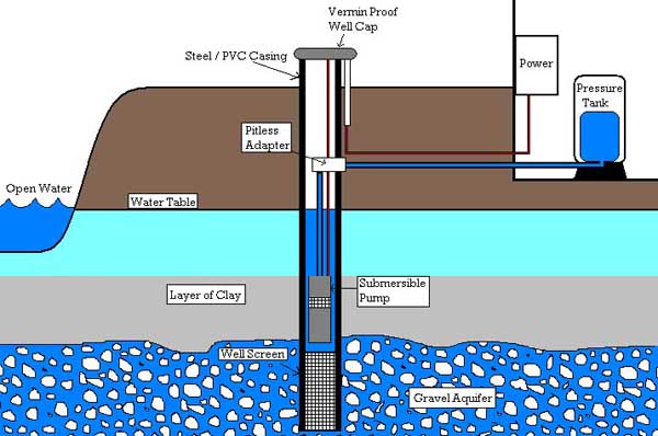
How A Water Well Works

Well Faq
How To Determine Your Well Pump Flow Rate On Wells With Pressure Tanks Residential Well Water Treatment Iron Filters Acid Neutralizers Chlorinators
Restoring And Testing Your Private Well After A Flood

Water Bore Drilling Companies Diagram Of Bore Water Drilling Drilling Companies In Remote Australia Direct Drilling

Water Well Diagrams Barbie Drilling Inc
Well And Pump Installations Axsom Franke Plumbing

Groundwater Or Artesian Water Extraction Concept Well Drilling Aquifer Infographic Diagram With Names Of Earth Layers Stock Vector Illustration Of Drink Rock 207884174

Drilled Well Construction Environmental Natural Resource Issues
1

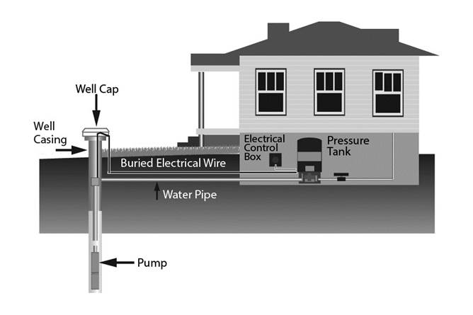
How A Well Water System Works Explained With Diagram
Water Well Location How To Find The Well

Artesian Water Well In Cross Section Water Resource Artesian Water And Groundwater Infographic Well Schematic Diagram Canstock

Well Diagram Michael Parsons Well Drilling

Modern Water Well Diagram Stock Photo Download Image Now Istock
2

Baker Water Systems Well Diagram

Simplified Diagram Of A Deep Water Well Download Scientific Diagram

Deep Well Pump Installation Diagram Deep Well Pump Well Jet Pump Jet Pump
Install A Well At A Water Project
Well Pump Prices Well Pumps Commercial Water Well Pumping Diagram

Clean Well Water Report Well Pump Pressure Tank Diagram
Standard Pressure Water Well Bee Cave Drilling


Comments
Post a Comment