39 fan coil unit diagram
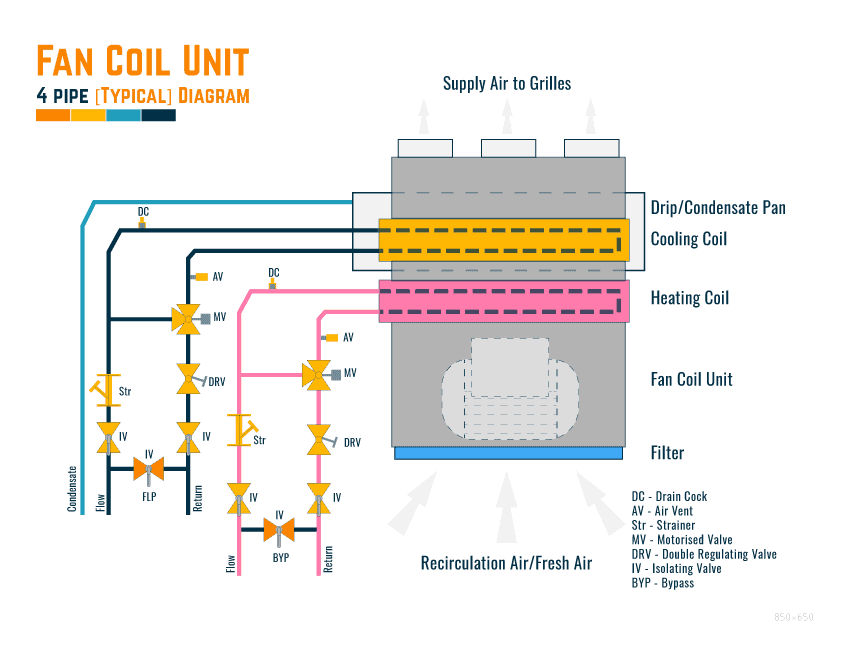
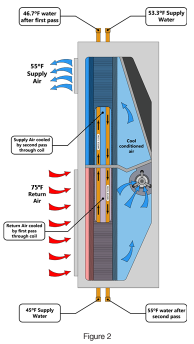
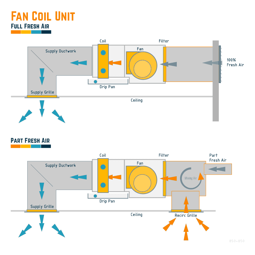
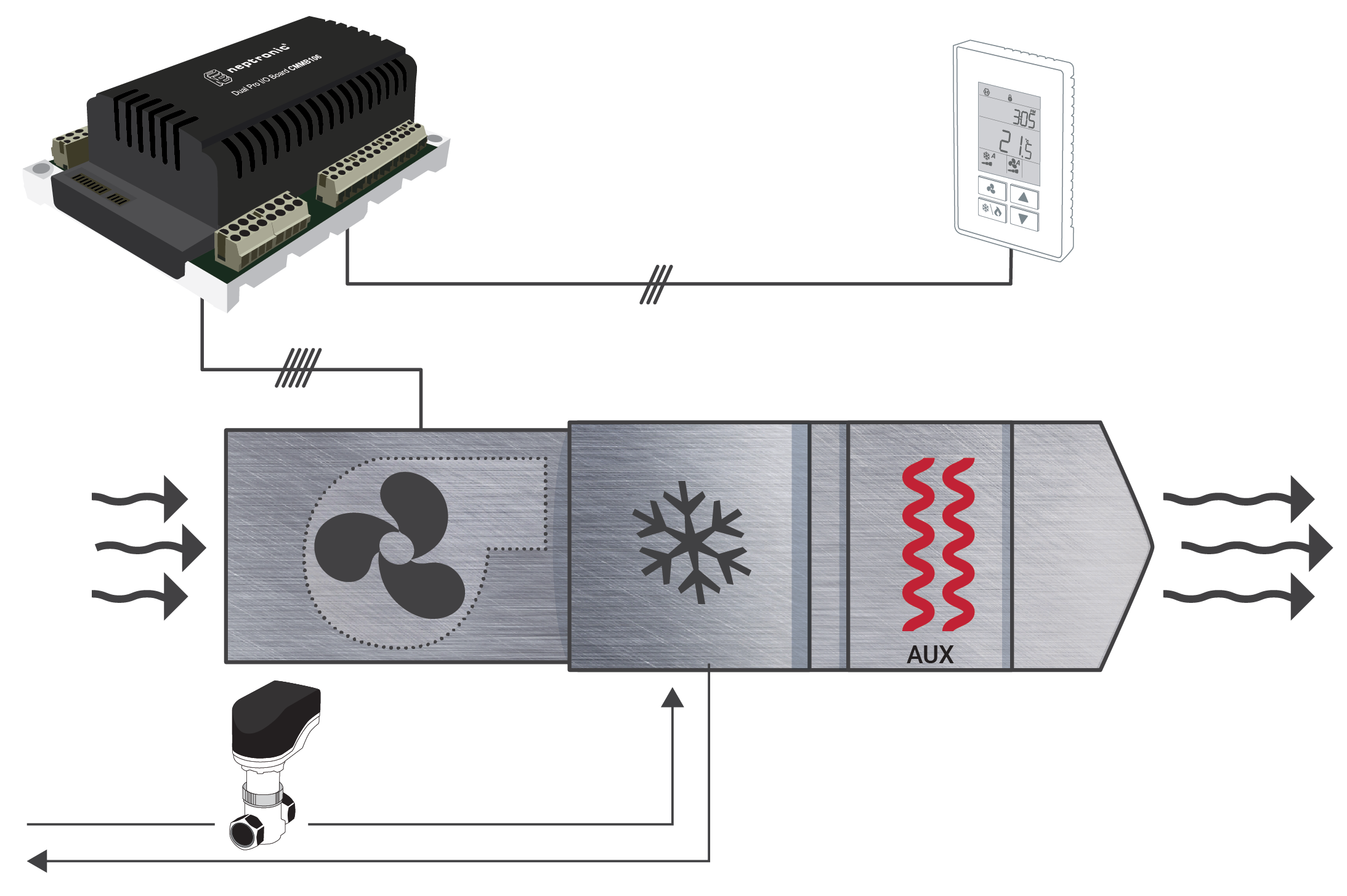
individual fan coil unit to deliver heat or cool as needed. Each fan coil unit contains two coils; one for the heating loop and one for the cooling loop. The thermostat determines if the cold loop coil or thehot loop coil is used. Each Suites fan has three fan speeds, low, medium and high, which are measured in CFMs. (Cubic Feet per Minute). Fan Coil Unit Diagram [Non-Ducted Recirculation] The below shows a typical fan coil unit that will use the ceiling as a return/recirculation plenum. *Note: there could be instances where a fresh air duct is connected to the unit to provide a minimal fresh air volume. This is usually a duct around 100mm in diameter.
Wi Fi Fan Coil Unit Programmable Thermostat For Carriar Trane York Fcu. Trane mcd524 50hz fan coil with line unitrane force flo air chilled water unit typical wiring diagrams 129 134 product catalog diagram full pdf free uni and manual furnace limit control troubleshooting xe1000 honeywell rth 7600 installation iom units hfce hfxe vfce vfxe cassettes ac motor heating hvac talk refrigeration ...

Fan coil unit diagram
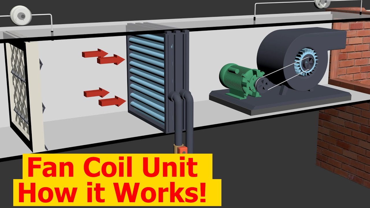
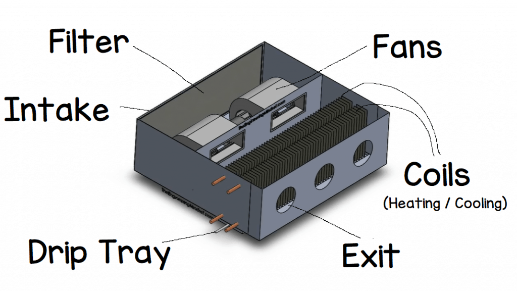
FCU. (fan Coil Unit ) Electric Wiring Diagram Related To #HVAC In Hindi\Urdu Air Cooled Chiller Working Linkhttps://www.youtube.com/watch?v=PzpItjxw7d0&t=28s... Draw-Though Unit or Blow-Through Unit In a draw-through unit the supply fan is located down steam from the cooling coil section as shown in fig air is drawn through unit coil section. Also the discharge air from the AHU can be easily connected to a supply duct of similar higher velocity. Drawn-through unit are the most widely used AHUs. In this video we take a look into HVAC fan coil units to understand how they work. Using 3D models, photos and diagrams to build your knowledge.LEARN MORE HE...
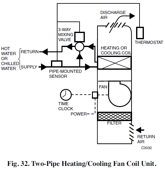
Fan coil unit diagram. diffuser, independent of the fan coil unit. This allows the fan coil unit to be turned off or run at low speed during part load conditions. Note that if a low supply air temperature (less than 55 °F) is required for dehumidification, a high induction diffuser should be selected to prevent drafts. Another option is to duct the outdoor air into ... issues. In the event the indoor unit is stopped for a prolonged period, with the fan stopped and circulation of cold water in the heat exchanger, condensation may also form on the unit's exterior. In this case it is advisable to install the 3-way (or 2-way) valve accessory in order to stop the flow of water in the coil when the fan is stopped. Fan Coil Unit (FCU) Fan Motor Control . Fan Relay Board 2 (FRBii) - Installation, Operation, and Maintenance . The Fan Relay Board assembly (FRBii) provides electronic control for the fan motor and various connections for peripheral devices. The FRBii accepts incoming single phase power of nominal AC voltages 120, 208, 240 and 277. Fan coil units are a highly efficient means of turning a water chiller or hot water boiler into an efficient, quiet air conditioning system. The units are super quiet because the only moving par t is the fan; making them ideal for use in offices, hotels and the home. The new range of fan coil units offers 5 models, of which 3 in flexible ...
April 21, 2021 on Fan Coil Unit Thermostat Wiring Diagram. In the most basic system this functionality is provided by use of a fan center relay and the low voltage wiring to the thermostat now will require a minimum of three wires for heat only units and four wires for heat cool fan for control. Hl series d horizontal low profile fan coil unit. Description: Wiring Diagram For Carrier Fan Coil - Readingrat pertaining to Fan Coil Unit Schematic Diagram, image size 639 X 600 px, and to view image details please click the image.. Here is a picture gallery about fan coil unit schematic diagram complete with the description of the image, please find the image you need. 22 VDC COIL TDR RELAY 4 22 VDC COIL BLK/WHT RED/WHT SEENOTE#4 OR OR RELAY1 6 8 LS4 4 2 L1 L3 L4 L2 L4 L2 1. Use Copper Wire (75ºc Min) Only Between Disconnect Switch And Unit. 2. To Be Wired InAccordance With NecAnd Local Codes. 3. IfAny Of The Original Wire,As Supplied, Must Be Replaced, Use The Same Or Equivalent Type Wire. 4. the 42C,D,V unit fan coils. Refer to the unit wiring diagram installed on the blower housing or specific manufacturer liter-ature for any other type of factory-mounted controls. See drawings for unit configurations, dimensions, clearances, and pipe connections. Refer to unit wiring label for all electri-
Horizontal Low-profile Units. These fan-coil units offer an optimized performance, which provide excellent indoor air quality. 250-1,200 CFM. ARI-440 certified and labeled. Flexible design. See Product Details. Johnson Controls. Installation dimension diagram . ... Fan Coil Unit Wall Mounted Type ... (1) To ensure the heat exchanging, the air in the fan coil of the unit must be ...32 pages Fan Coil Units. Minimum noise. Minimum space. Maximum options. No other selection of fan coils is more complete than Carrier's AirStream™ product line. With everything from belt-drive to ducted units and unique stackable configurations - all in multiple models and capacities - AirStream units offer exceptional flexibility and availability. according to the wiring diagram. • The unit must be GROUNDED to prevent possible hazard due to insulation failure. • All electrical wiring must not touch the water piping or any moving parts of the fan motors. • Confirm that the unit has been switched OFF before installing or servicing the unit. • Risk of electric shock, can cause ...
Fan Coil Units Probalance From Crane Fluid Systems
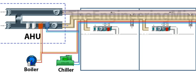
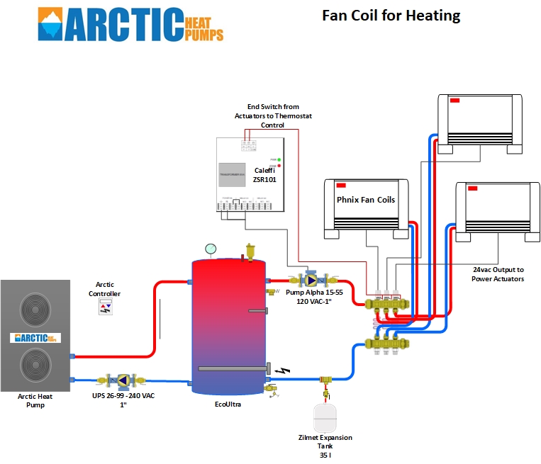
Fan Coil Units in combination with chillers and or boilers can be used to provide a broad range of solutions that can be tailored to local conditions such as climate, primary fuel market or building insulation. In warmer climates or when a building is well insulated, Fan Coil Units with a chiller (2-pipe system) can handle both cooling and heating.
Hvac Fcu Fan Coil Units Valve Connection Installation Details Youtube
1 - Check the equipment is disconnected and completely isolated from the power supply. • 2 - Ensure a wiring diagram is available, or note the wiring ...44 pages

Fan Coil Unit An Overview Sciencedirect Topics
Fan Powered Air Terminal Unit Control Diagram: PDF. SD233600-04: Duct Connection - Air Terminal Units: PDF. SD233600-05: ... Heating Only Fan Coil Unit Controls: PDF. SD238200-03: Four Pipe Fan Coil Unit Controls: PDF. SD238200-04: Hot Water Cabinet Unit Controls: PDF. SD238200-05:

Fan Coil
INTERNATIONAL COMFORT FAN COIL INSTALLATION MANUAL [PDF] - Model: FVM4X "B" Series, (2016) International Comfort Products, Lewisburg TN 37091 USA; INTERNATIONAL COMFORT HORIZONTAL FAN COIL UNIT WIRING DIAGRAM MANUAL [PDF] - Models FMC4, FMU4, WAMC, WATC, (2017) International Comfort Products, Lewisburg TN 37091 USA
Working Principle Of Fan Coil Unit Youtube
Inside each suite is a Fan coil unit that is controlled by the suite's thermostat. Each Suites fan has three speeds, low, medium and high, which are calibrated to deliver different air flow quantities, in CFMs. (Cubic Feet per Minute). ... Diagram 1: High Overview of the system . Diagram 2: Tenant Suite
V1 Cecdn Yun300 Cn
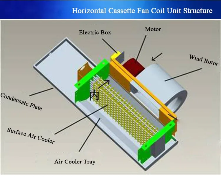
Fan coil units can be vertical units which sit right on the floor or they can be horizontal units hung from the ceiling. The horizontal units can be above a dropped ceiling. Below are diagrams, some samples of performance for different types of fan-coil-units. Sizes and weights are given in some of the performance/specs charts
Wineguardian Com
Chilled Water Fan Coil Unit Piping Diagram. Water cooling for buildings cdw chilled water schematics the water piping and pumps horizontal high performance fan coil fan coil unit coolers. Chilled water fan coil units for and residential use fcu chilled water piping connection detail cadbull new fan coil piping package.
Fan Coil Unit Fcu Hvac Youtube
Inside the air handler unit, the high voltage wiring powers the indoor fan, the heater and provide power for the transformer. Inside the condenser/evaporator unit, the high voltage wiring powers the outside fan and the compressor. 3- Low voltage control part: This part has (2) mode for operation which are:
Fan Coil System Hvac
Basic series fan-coil units are single room air conditioners designed for cooling and heating load capabilities of 400 to 800 cfm. Units can be selected with either one hydronic circuit (2-pipe) or two hydronic circuits (4-pipe) coil connections. The Basic Series Fan-Coil design is for the market that requires only

Fan Coil
About fan coil units Essentially made up of a motor with a fan, a heating or cooling coil connected to the building's central hot water and cold water system, and controller, a fan coil unit is simple heating and cooling device. It is designed to heat or cool the specific space where it is installed and, since it is typically not connected to

Mep Work Fan Coil Unit Fcu Hookup Facebook
20 Fan Coil Unit Diagram Wiring Niche. Study On A Fan Coil Unit And Chiller By An Intelligent Control Method With Stepless Variable Sd Driving Technology Sciencedirect. Inlet Of Er Fan Coil Unit Diagram Schematic And Image 04. Fancoil Details Detail For Designs Cad. A schematic diagram of fan coil unit three pipe system redrawn scientific ...
2 Pipe Versus A 4 Pipe System Campus Housing
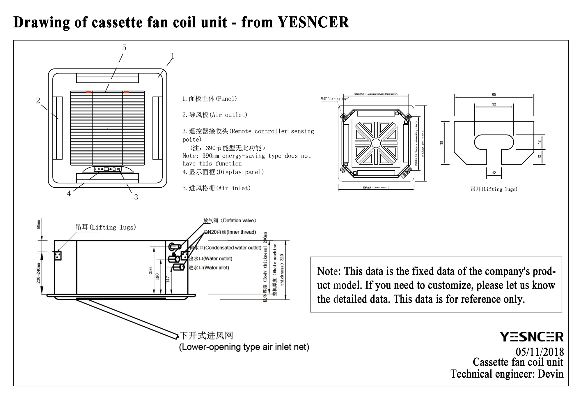
Cassette Type FCU - TKM. 15. Ceiling & Floor Exposed FCU - TC. 18. Wiring Diagrams. 20. Installation. 23. Maintenance and Service. 24. FAN COIL UNIT.
Fan Coil Units What Where How Constructandcommission Com
Download scientific diagram | A schematic diagram of a fan coil unit. Readapted from [5]. from publication: Central Air Conditioning: Systems and ...
Vertical Console Fan Coil Units From The Whalen Company Hvac Industry Pioneer In Commercial Fan Coil And Heat Pump Systems
instructions for the 42TW unit Fan Coils. Refer to the unit-wiring diagram installed on the ... 42TW fan coil units are shipped individually.16 pages
A Schematic Diagram Of A Fan Coil Unit Two Pipe System Of Direct Download Scientific Diagram
A.The Fan Coil Unit is controlled by a unit mounted controller provided by Mechanical Systems Controls Contractor (MSCC). B.On a call for cooling, the thermostat signals for the heating control valve to modulate toward the closed position. On a further call for cooling, the thermostat signals for the fan to speed up from its

Fan Coil Systems Hvac Ekinex
Shop drawings shall be submitted the following for each fan-coil unit type and configuration: a. Wiring diagrams indicating power, signal and control wiring ...

Horizontal Fan Coil Unit Detail Cad Template Dwg Cad Templates
HPF/HPP/HPE Horizontal High Performance Fan Coil Unit INSTALLATION, OPERATION AND MAINTENANCE MANUAL Stock ID: IOM-FCUHP April, 2008 ©2008 Environmental Technologies Largo, FL • Part No. PX-00-0163

Pin On Are Prep
In this video we take a look into HVAC fan coil units to understand how they work. Using 3D models, photos and diagrams to build your knowledge.LEARN MORE HE...

5 A Fan Coil Unit Fcu 11 Download Scientific Diagram
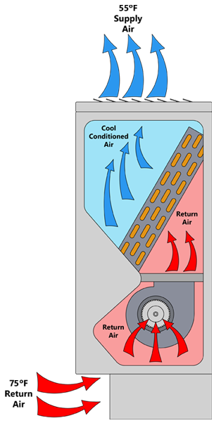
Draw-Though Unit or Blow-Through Unit In a draw-through unit the supply fan is located down steam from the cooling coil section as shown in fig air is drawn through unit coil section. Also the discharge air from the AHU can be easily connected to a supply duct of similar higher velocity. Drawn-through unit are the most widely used AHUs.

Terminal Unit 4 Way Cassette Fan Coil Unit With Ec Motor
FCU. (fan Coil Unit ) Electric Wiring Diagram Related To #HVAC In Hindi\Urdu Air Cooled Chiller Working Linkhttps://www.youtube.com/watch?v=PzpItjxw7d0&t=28s...
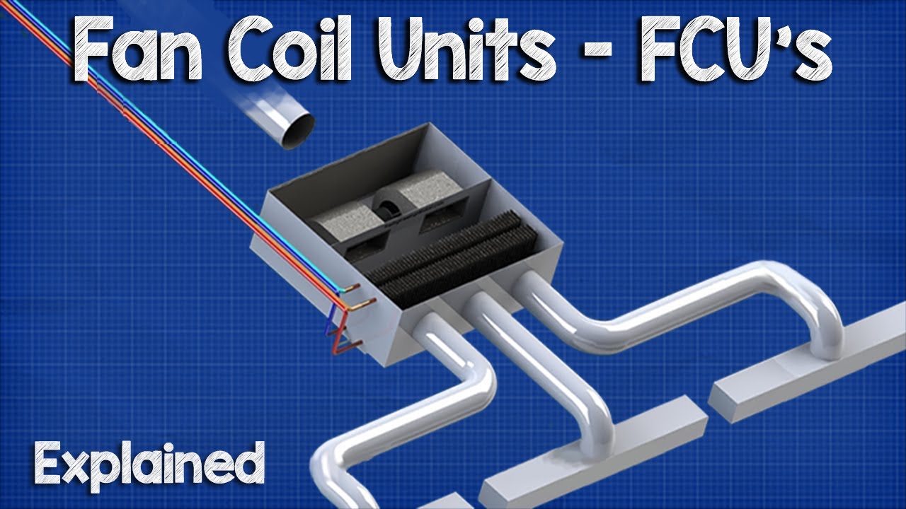
Fan Coil Units Fcu The Engineering Mindset
Riser Fan Coil Systems And Products From The Whalen Company Hvac Industry Pioneer In Commercial Fan Coil And Heat Pump Systems

All Water System Fan Coil Units Download Scientific Diagram

Fan Coil Unit Drawing
1

Fan Coil Unit System For Hvac Paktechpoint
Hydronic Fan Coils
Neptronic Com

Basic Configuration Of A Horizontal Fan Coil Unit Bsria 45 Download Scientific Diagram
Fan Coil Unit Drawing
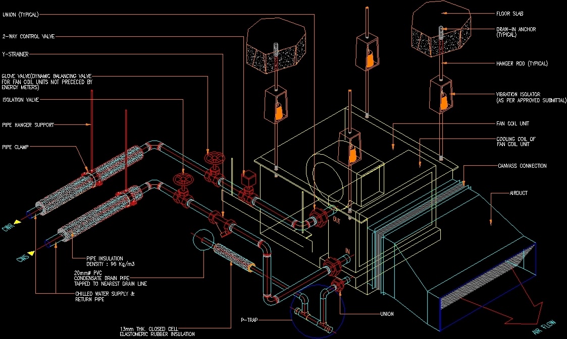
Fancoil Details Dwg Detail For Autocad Designs Cad
Fan Coil Units What Where How Constructandcommission Com

Hvac Apparatus With Hrv Erv Unit And Vertical Fan Coil Unitaanm Zorzit Vittorioaaci Woodbridgeaaco Caaagp Zorzit Vittorio Woodbridge Caaanm Chu Shengaaci Scarboroughaaco Caaagp Chu Sheng Scarborough Ca Diagram Schematic And Image 04
Fan Coil Units Fcu The Engineering Mindset

A Fan Coil Unit Fcu Is A Simple Device Consisting Of A Heating And Or Cooling Heat Exchanger Or Coil And Fan It Is Part Of An Hvac Syst Cửa Sổ Ly
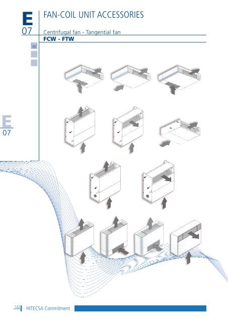
Fan Coil Unit Accessories Hitecsa
Daikin Horizontal Inverter Fan Coil Unit With Heating Cooling Buy Inverter Fan Coil Unit Horizontal Fan Coil Unit With Heating Cooling Daikin Fan Coil Unit Product On Alibaba Com

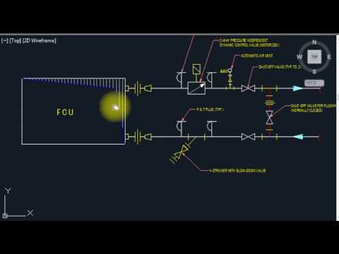
Piping And Instrumentation Diagram Fan Coil Unit Pump Plumbing Fan Angle Technic Bathroom Png Pngwing
Controls Fan Coils


Comments
Post a Comment