38 vaccum line diagram
lol there's no vacuum line diagram because there's a sum total of about 3 lines. There's the big ones that go to the booster and evac, and one little one for the fuel pressure regulator. Think that's it. Show us a pic. Iv'e been looking around for a vacuum line diagram for a 4.2L I6 and I can't seem to find one. Jul 3, 2021 — LOL. Should have looked here when I was tracing the dry rotted vacuum lines by hand. 1996 Tbird.
It has diagrams for vacuum lines. Read full answer. Jun 02, 2009 • 1986 Chevrolet S-10 Blazer. 1 helpful. 1 answer. Small vacuum lines to air cleaner of carburated 2.0 liter Honda. These are a vacuum line nightmare. I take it the diagram isn't still on the bottom of the hood?

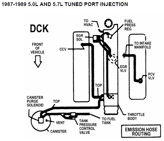
Vaccum line diagram
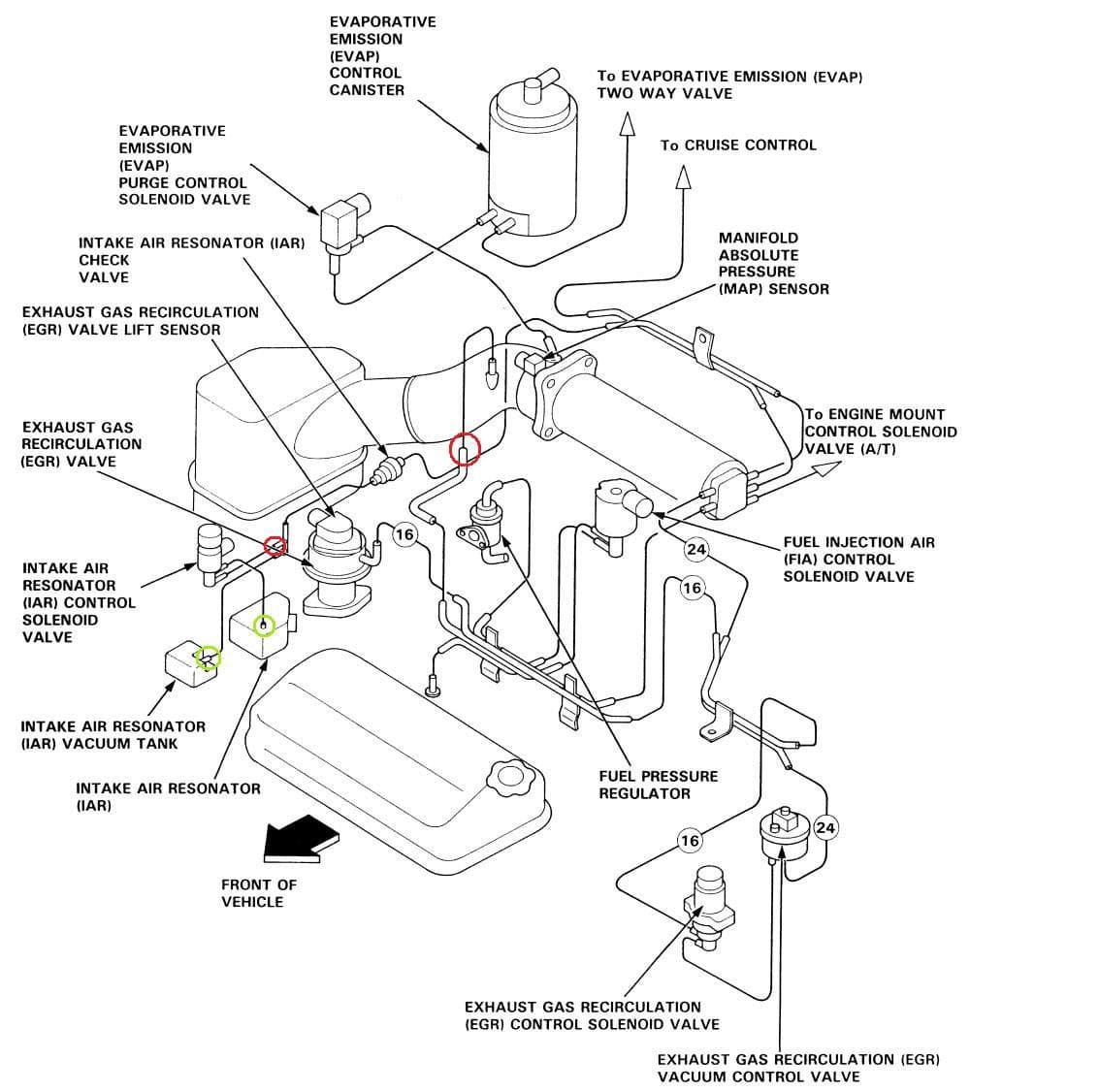
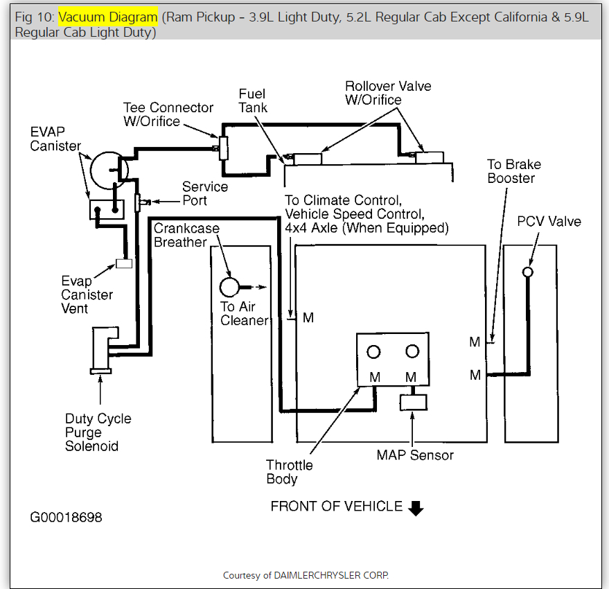
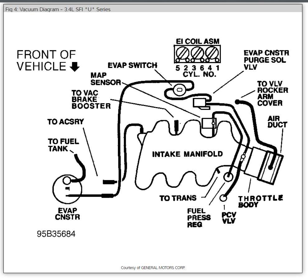
Re: Vaccum Line Diagram. KEY TO DIAGRAM ABOVE for AWM motor. Connection diagram for charge air control and vacuum pressure control. 1 - to EVAP canister. 2 - EVAP Canister Purge Regulator valve -N80-. 3 - Non-return valve for EVAP canister. Between EVAP canister and intake line in front of exhaust turbocharger. Here is the vacuum line diagram for your car. Check out the diagrams (Below). Please let us know if you need anything else to get the problem fixed. Image (Click to enlarge) SPONSORED LINKS. Was this . answer. helpful? Yes. No-1. Saturday, April 2nd, 2011 AT 11:12 PM Vacuum schematic for dodge ram 1500. Theres a small line together w the throttle linkagei cant seem to find its. 1997 dodge ram 1500 laramie slt 59 ltr. Check out the diagrams below. 1999 dodge ram 4x4 vacuum diagram my 4x4 will not engage when i shift into 4x4 high or low.
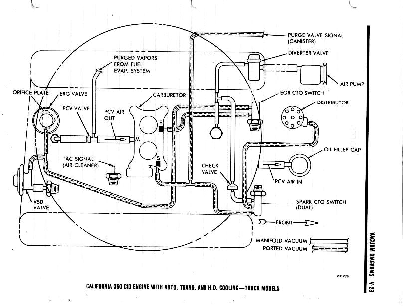
Vaccum line diagram. 0. Trophy Points: 45. Location: Chincoteague, Virginia. Vehicle: 1971 Maverick Grabber. Does anyone have any vacuum line diagrams for a 1974 Mav with a 250? Thanks. AutoZone Repair Guide for your Emission Controls Vacuum Diagrams Vacuum Diagrams. Mar 30, There are more vacuum ports on the Quadrajet then on the Instead of trying to find a vacuum line for each port on the carb to attach to.Oct 03, · my vacuum advance is fed from the front of the carb via a steel and rubber line. the T: right goes to the ... Vacuum diagram for dodge ram magnum - Dodge Cars & Trucks. Posted by Anonymous on Jan 13, Want Answer 0. Clicking this will make more experts see the question and we will remind you when it gets answered. Comment; SOURCE: vacuum hose schematron.org ram,,4x4,l. Apr 21, · I need a vacuum system diagram for a Dodge Ram truck with the smaller v8 ... Vacuum line diagram for 98 4 X 4 Ford Expedition. 1 - 2 of 2 Posts. Ask Your Own Ford Question. I replaced all vacuum lines and still had the problem. 800 x 600 px sourceOn this page is a list of areas covered by the 1968 Mustang wiring and vacuum diagrams.
This article contains underhood views or schematics of vacuum hose routing. Use these vacuum diagrams during the visual inspection in appropriate BASIC ...56 pages Vacuum Routing Diagram For 1987-93 Fox Body Mustang. Often times, enthusiasts have a difficult time understanding all of the different vacuum components on their Fox Body. Check out LMR's very helpful article listing the main areas that experience the most problems. We at Late Model Restoration have replacement parts for any area of concern. FINALLY, a Vacuum Hose Diagram Topic is solved. This is for a '98 T-5. Others will vary but the same or similar to most 850 turbo's. The designed changed with later S/V/70's so be aware. I got so darned frustrated trying to see this intsy bittsy diagram under the hood of the car, so I finally took a decent digital picture today. 1979 Ford 351m Vacuum Diagram. My truck is 30 years old and a previous owner has "tinkered" with the engine bay in the pastto say the leastit gives me a headache just. i have a F with a M.i got it from a friends dad after it had a edelbrock schematron.org problem is vacuum schematron.org everywhere!i. Vacuum hose schematic low altitude engine ...
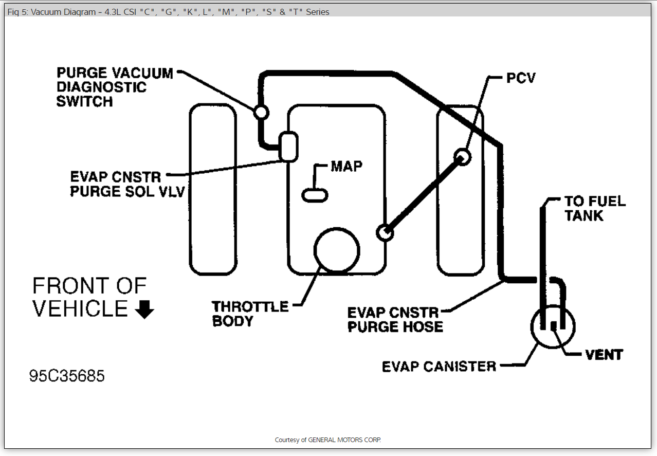
Vacuum lines dry out and crack over time. Often they are routed under the intake and/or close to HOT exhaust. Here is a quick tip that can help you route t... Vacuum Hose Diagram. Vacuum line diagram, routing. GGOODALE MEMBER; 1996 MERCURY SABLE; 3.0L; 6 CYL; 2WD; AUTOMATIC; 133,000 MILES; Need to know where the vacuum lines hook up coming out of the intake manifold. Specifically there is an elbow that has three connections that hooks to the manifold. Need to know where they go to. Access our free Vacuum Diagrams Repair Guide for GM Full-Size Trucks 1988-1998 through AutoZone Rewards. These diagrams include: Fig. 1: 1988-89 (VIN Z) C/K series with 4.3L Sep 25, 2018 - Tech / General Engine - Vacuum Lines Diagrams!!! I GOT THEM ALL!!!!! - I just collected ALL vacuum lines from 82 - 92 TG F-Bodies!
Quadrajet Vacuum Line | Page 2 | NastyZ28.com
Article about Automotive Vacuum systems, how they function and what is there purpose. Also how to repair and find vacuum diagrams and hose routing for your ...
Vacuum Lines Diagrams!!! I GOT THEM ALL!!!!! - Page 5 ...
Minimize Gurgling in Vacuum Lines All Vertical Wet lines are 1/2" Trunk Lines: Follow Sizing Guide Under Floor Installation and Add One User Vacuum Piping to be Type M or Schedule 40 PVC Maintain a 1/4" Slope per 10 feet of Piping (toward pump). Always Stagger Branch Lines From Main Trunk, Do Not Use 4-way Cross Fittings. Use 45 0 Y's and

I just need the complete vacuum line diagram for a 97 f250 ...
Apr 12, 2011 — Series I Tech Garage - Vacuum hose diagram - Please I need a vacuum hose diagram for my 2006 RX8(automatic). I live in a small island and ...
95 Accord Ex f22b1 vacuum line diagrams? - Honda-Tech ...
Wiring & Vacuum Diagrams...and much more!! This product includes - Colorized wiring diagrams - Vacuum diagrams - Vol. III 1972 Car Shop Manual, Electrical - Electrical Illustrations - How to Read Wiring Diagrams training course 5236 Licensed and approved by the Ford Motor Company 1972 Free Bonus! 30-Minute Video Ford Training Course 13001, Vol ...
I Need a Vacuum Diagram: Two Lines Between the Engine and ...
Nope no vacuum line diagram that I know of. But basically it is fairly simple. A line comes off the intake manifold and splits off at a tee, one goes to the carb, and one to the fuel pump, another tee or line off the manifold would have a line going to the PAIR air valve and maybe a vacuum line going to the fuel tank carbon canister (depends on if you are in Calif
Vacuum Line Routing: Engine Performance Problem Vacuum ...
The Pink Vacuum Line goes from the TAB Solenoid (driver's side rear solenoid) to the passenger side (adjacent to the Vacuum Reservoir Can) and down to the bottom of the TAB (Bypass) Valve. Note that my Pink Vacuum line appears Yellowish in this pic and is not yet connected to the base of the TAB Valve as I was working up a solution at the time.

I need a vacuum line diagram for MB 350S turbo diesel (1993)?
VACUUM HOSE PIPING DIAGRAM. <4B11-Non-turbo> <4A91-M/T> <4A91-A/T, 4A92> <4B11-Turbo> <4B10-Except low CO <4B10-Low CO.

srt4 turbo vacuum diagram - Dodge SRT Forum
413 Posts. #3 · Jul 8, 2010. ^^^X2. If you have a J-code engine and a Turbo 400 automatic, there's only one vacuum line from the vacuum pump to the vacuum regulator valve at the injection pump, then another from the top of that valve to the vacuum modulator on the transmission. If you have a C-code engine, there will be a pair of solenoids on ...
Vacuum Hose Routing Diagram: I Need to Replace Crummbling ...
Vacuum Hose Routing Diagrams. Below is a list of all vacuum diagram that are currently available. Make sure you look at the correct diagram for your engine ...

Gas Line From Tank- Help - Yamaha Rhino Forum - Rhino ...
Registered. Joined Jan 15, 2012. ·. 137 Posts. Discussion Starter · #1 · Oct 9, 2013. Anyone have a vacuum line diagram, hand written or factory diagram? I gotmy rebuilt motor in and even ran it for 30 minutes but my vacuum lines are not correct. I'm really wanting to get this thing smog checked and licensed (on non-op right now) tomorrow ...

1986 Chevy S10 Vacuum Line Diagram - Wiring Forums
First , find the problem area on the Vacuum diagram. Highlight the individual area. Trace the Vacuum till you can see where a problem may have taken place. Eliminate each portion of the diagram in sections until you find the leak in the Vacuum. This makes knowing where to check connections easy with an automotive Vacuum diagram.

I need a vaccum diagram for a n 85 mercedes300sd
SOURCE: 87 chevy s10 4x4 vacuum diagram NOTE<< If Picture Does Not Show Please Email Me @ [email protected] And I Will Send it to You It IS DETAILED And COMPLETE Diagram of Exactly What You Ask For. Vacuum and Vapor Hose Diagrams Notes Vacuum Actuation System . Posted on Feb 13, 2009

Vac/Boost Diagram - D-series.org
Looking for a vacuum hose diagram for a 2004 Silverado 1500 6.0L I can hear a vacuum leak on the drivers side of the engine, cannot pin point it but my truck has 370,000km so ill just replace all the vacuum lines Did a vacuum leak test, i sit from 15-16.8 psi jumps back and forth in that area as ...

1995 Isuzu Rodeo, 3.2 has missing vacuum line off ...
Registered. Joined May 29, 2004. ·. 860 Posts. #3 · Apr 25, 2010 (Edited) Only show this user. memphizballa said: I Need A Vacuum Diagram Of The Passenger Side Of A 96 Impala Ss, Labeling Where The Vaccuum Lines Go From The Passenger Side Of The Top Of The Motor. Thanks.
Vacuum Hose Routing Diagram: I Need to Replace Crummbling ...
The size of the vacuum line is 3/16 price around $6 on amazon http://amzn.to/2hhWcMvDonate to Virberello for Parts https://rb.gy/gzrtitChinese Sco...

Ford F 150 Efi Vacuum Lines Diagram - Wiring Forums
vaccum line diagram. Jump to Latest Follow 1 - 8 of 8 Posts. awake1630 · Registered. Joined Dec 31, 2006 · 1,103 Posts . Discussion Starter · #1 · Jul 12, 2010. Only show this user ...
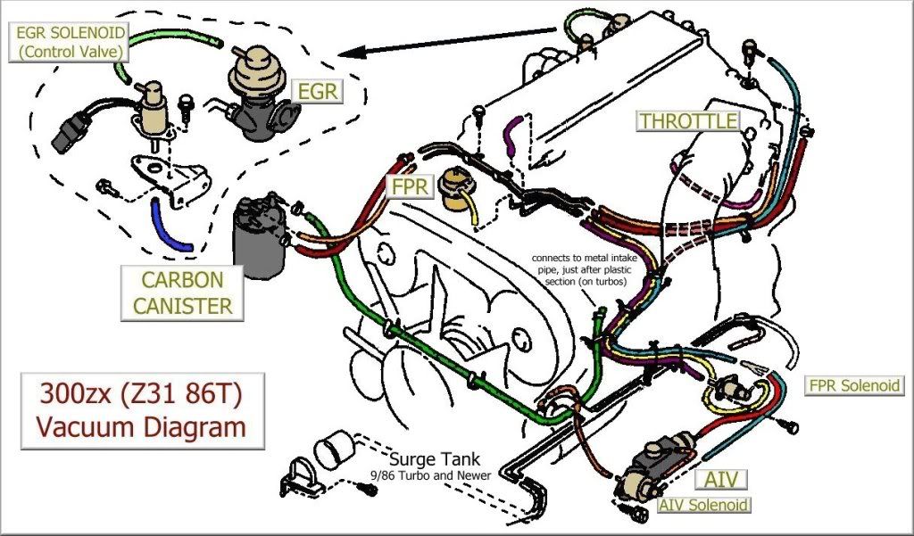
Ka24de Vacuum Line Diagram
The Green line goes to the rear nipple where you have the Blue line. The Blue line doesn't go directly to the turbo housing as your diagram indicates, it goes to a T just before the turbo housing. The other leg of the T leads to the vacuum ejector. M MikeRT4 Registered Joined Feb 1, 2009 487 Posts #4 · Oct 18, 2011

I would like a diagram of the vacuum system for a 2000 ...
Datsun vacuum hose diagram z related problems. Ask your Datsun vacuum hose diagram z questions. Get free help, advice & support from top Datsun. I am trying to get all my vacuum lines in the correct location to make sure that prior to me owning it and that is why i am looking for the diagram.Need a vacuum diagram for a datsun diagramweb.net ...

I NEED A VACUUM LINE DIAGRAM FOR A 1998 ASTRO
Dec 30, 2012 — Hi, I have been searching all afternoon with no luck so I thought I would ask. Does anyone have a vacuum line diagram for a 77 w/350?vacuum linesJul 18, 2008Vacuum line schematicSep 23, 2003More results from www.elcaminocentral.com
Vacuum Line Diagram: I Recently Replaced the Stock 305 ...
Vacuum schematic for dodge ram 1500. Theres a small line together w the throttle linkagei cant seem to find its. 1997 dodge ram 1500 laramie slt 59 ltr. Check out the diagrams below. 1999 dodge ram 4x4 vacuum diagram my 4x4 will not engage when i shift into 4x4 high or low.

P1479 P0171 P0174 - Club Touareg Forums
Here is the vacuum line diagram for your car. Check out the diagrams (Below). Please let us know if you need anything else to get the problem fixed. Image (Click to enlarge) SPONSORED LINKS. Was this . answer. helpful? Yes. No-1. Saturday, April 2nd, 2011 AT 11:12 PM

Where does the vacuum line for a 1996 Ford E-150 III van ...
Re: Vaccum Line Diagram. KEY TO DIAGRAM ABOVE for AWM motor. Connection diagram for charge air control and vacuum pressure control. 1 - to EVAP canister. 2 - EVAP Canister Purge Regulator valve -N80-. 3 - Non-return valve for EVAP canister. Between EVAP canister and intake line in front of exhaust turbocharger.

Vacuum/Air Line Diagram - Pelican Parts Forums

I need a diagram of the vacuum/emission lines for a 1979 ...
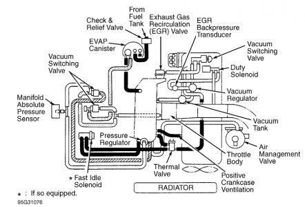
Quadrajet Vacuum Diagram

Buick Terraza Vacuum Line Diagram - Wiring Forums

Vacuum lines on 1985 GMC Sierra - Ask the GM Technician ...

January 2019. Cleveland, OH.

Need vacuum line diagrams for 1988 Jeep Wrangler 4.2 6cyl ...
Vacuum line diagram | Lincoln vs Cadillac Forums

27 2002 Chevy S10 Vacuum Line Diagram - Wiring Diagram List

The view from the high line in Manhattan NYC.

Sitting in LA
1jzgte Vacuum Diagram
![[MC_6946] Gy6 Engine Vacuum Diagram Free Diagram](https://static-cdn.imageservice.cloud/2061706/50cc-scooter-fuel-line-diagram-free-download-wiring-diagram.jpg)
[MC_6946] Gy6 Engine Vacuum Diagram Free Diagram
Engine - Explorer intake vacuum line diagram | StangNet
VACUUM LINES - Nissan Forum

Beetle Hose Lines


Comments
Post a Comment