40 defrost timer wiring diagram
Defrost Timer Wiring Diagram, furthermore 2 2 ecotec timing marks diagram together with wiring diagram for intermatic t pool pump along with refrigerator ptc relay furthermore walk in freezer defrost timer wiring diagram together with dodge ram radio wiring diagram furthermore domestic refrigerator wiring as well as plant cell. After getting wiring diagram off internet it was diagnosed as freezer stuck in defrost mode, temp alarm on, but fan running. Turned gray knob on defrost timer (located bottom left back of freezer) past defrost position to verify compressor would run...it would not, but fan would run.
W10822278 Wiring Diagram. Kenmore Refrigerator Defrost Timer W - This eight-hour defrost timer So I figured my model was too old, the wiring diagram was simalar to mine on. I do not have a wiring diagram. ANSWER Hello Ken, You will need to connect the black jumper wire on the defrost timer W to pin. Whirlpool W Refrigerator Defrost Timer ...

Defrost timer wiring diagram
How you diagnose a non-starting compressor depends much upon whether you have a mechanical defrost timer or ADC (Adaptive Defrost Controls.) If you have a fridge with ADC and the lights are on, and the compressor will not start, you need to check if you're getting voltage to the compressor starting components as described in Section 5-3(b). The Latest Paragon® Defrost Timer • Universal Defrost Timers (UDT) • Works with multiple voltages • Removes built up of ice and frost • Easy to install • Simple to program • Part 9145-00 temp terminated • Part 9045-00 time terminated • Available as mechanism only without case - Add "M" to end of part number Here is a picture gallery about 20 wiring diagram complete with the description of the image please find the image you need. Paragon defrost timer wiring diagram paragon defrost timer wiring regarding 8145 20 wiring diagram image size 577 x 600 px and to view image details please click the image. 8145 20 8000 series defrost timers the paragon ...
Defrost timer wiring diagram. Paragon 00 Wiring Diagram Defrost Timer Circuit Evaporator. The Paragon® Series Auto Voltage Defrost Timer is designed for commercial freezers Wiring Diagrams. AV. AV Heavy-duty steel case with electrical knockouts in the sides, Specifications. Operating Voltages: or / VAC, 60 Hz HEATER. DEFROST TIMER WIRING DIAGRAM SPECIFICATIONS Input • Voltage: 18-30 VAC • Frequency: 50-60 Hz • Power Consumption: 1 watt maximum Output • O, W2: – Type: Relay – Form: DPST, normally open – Rating: 2 amps @ 30 VAC • DF1, DF2: – Type: Relay – Form: SPST, normally closed – Rating: 1/2 HP @ 240 VAC Time Delays 21.10.2017 · Western Fisher 3 Plug Isolation Module Wiring Diagram. Homesteader vehicle side harness fisher minute mount pump wire diagram electrical components hd2 snow plow ez v xv2 original wiring relay style fleet flex 3 port 2 plug truck kits not dropping float fixed it 79147 service manual snowplow help problems no power to isolation module xtremev western 11 pin the later … Walk in freezer wiring diagram. Retail store walk in coolers and freezers boiler operating control used as a thermostat universal defrost timer wiring. Wiring diagram a schematic drawing of the wiring of an electrical system. This type of wiring diagram has branch runs all shown as parallel circuits going from the left line l1 to the neutral ...
Joined: 11/5/2011 (UTC) Posts: 2. The part replacement for the defrost timer has a black wire that was not on the original part. I have confiremd that this is a replacement but the are options for the black wire depending up the original wiring diagram of the unit. I chose version2/procedure 3 as it seemed to fit. Source: www.beautyboss.co.id I know when we draw up the schematic diagram the. Older frigidaire defrost timer 8000 series auto voltage in frost free refrigerator wiring diagram precision multiple controls official paragon 632 20 fixed frt045gm question servair ltd air time hvac r older frigidaire defrost timer doityourself com community forums installation data 8000 series auto voltage defrost ... Whirlpool Refrigerator Water Line Diagram. 3 Wire Defrost Termination Switch Wiring Diagram. Lg Inverter Refrigerator Wiring Diagram. Ge Monogram Refrigerator Wiring Diagram. 8 Pin Timer Relay Wiring Diagram. Whirlpool Gas Dryer Wiring Diagram. Lg Double Door Refrigerator Wiring Diagram. Frigidaire Refrigerator Compressor Wiring Diagram. After fixing a defrost problem, keep an eye out for signs of a recurrence for at least a week. The sooner you catch it, the less ice you'll have to melt. 7) You may stop the compressor from running using the defrost timer or cold control, by cutting off the power to the fridge, or simply by pulling the plug out of the wall.
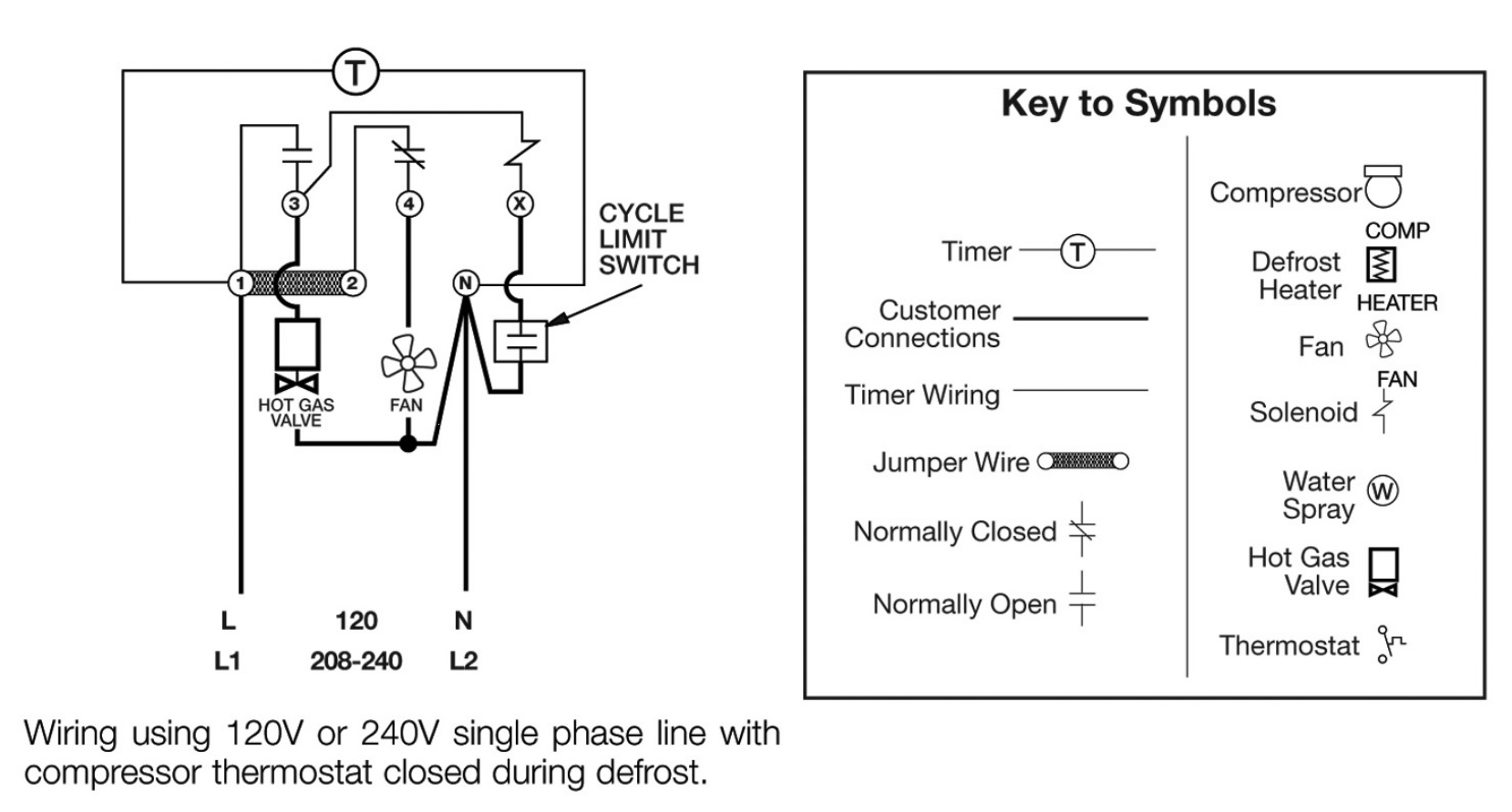
After getting wiring diagram off internet it was diagnosed as freezer stuck in defrost mode, temp alarm on, but fan running. Turned gray knob on defrost timer (located bottom left back of freezer) past defrost position to verify compressor would run...it would not, but fan would run. Jul 03, 2019 · Walk In Freezer Defrost Timer Wiring Diagram Do not set a cooler thermostat below the walk-ins design temperature or product Diagram 9 - Typical Wiring Diagram for Single with Defrost Timer Only. The most common form of defrosting a freezer's unit cooler is done by control for the evaporator is wired to terminal “X” on the defrost timer. In this video you can learn about the defrost timer wiring diagram of a frost free refrigerator and circuit diagram Step by step details about the function o... These timers are adjustable from one to six cycles per day. A minimum of four hours is required between successive operations. Defrost duration ranges from 4 to 110 minutes in 2 minute increments and is easily adjustable. Time initiation, temperature or pressure termination; Contact rating: 40 amps resistive/pole
2Pcs Refrigeration Accessories for Refrigerator Defrost Timer ...
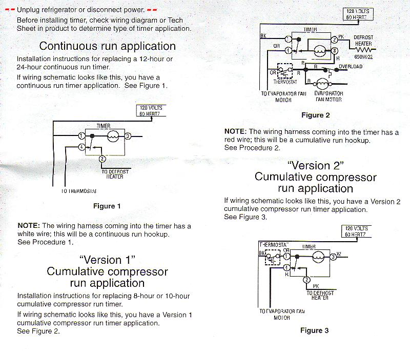
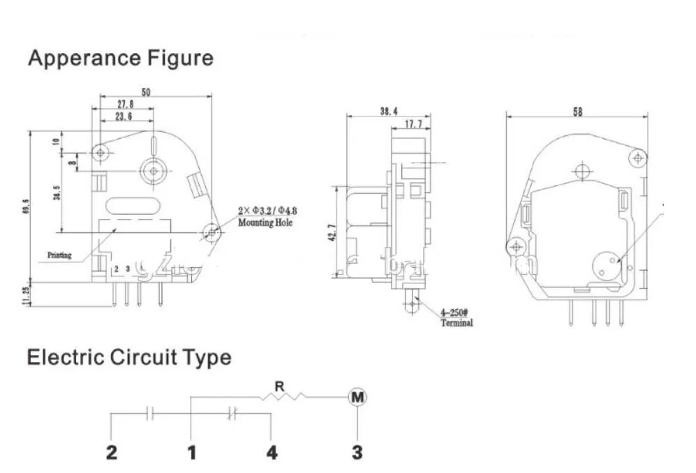
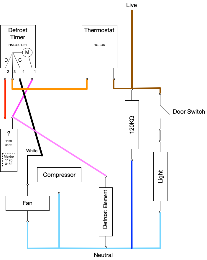
Whirlpool defrost timers only! When I was a little unsure about hooking those defrost timers up, where the timer motor wire went , #1 terminal or # 2 terminal. Whirlpool tech line gave me an easy way out: If the timer has a WHITE wire going to it ,the timer lead goes on #1 Anything else goes on #2

30 Unique Refrigerator Start Relay Wiring Diagram- A control ...
timer only advances when the compressor is running. After the timer measures an accumulated run time equal to a predetermined amount, the system will enter into the defrost cycle. This type of defrost is often referred to as a cumulative run-time defrost. Even the cumulative defrost systems fail to account for the number of times the door is opened
Defrost Timer (R 8004-TMDE706SC) refrigerator Defrost Timer ...
The Paragon® Series Auto Voltage Defrost Timer is designed competitive voltage-specific mechanical defrost timers, eliminating Wiring Diagrams. Simple wiring. Resources: Paragon sell sheet shows model numbers and wirings diagrams, Replace with TT or CT series. The Paragon® defrost and the Tork® electric timers offer versatility and ...
FIXED - FRT045GM Defrost Timer Question | Page 2 ...
Defrost Termination Thermostat Wiring Diagram. In a common wiring diagram for a time-initiated, temperature-terminated electric defrost system the time motor (TM) is energized continuously. Is there a reason they can't include a wiring diagram of the switch in the interlink 3 wire defrost termination switch with black and blue wires in.

Refrigerator Defrost Cycle | Appliance Aid
6.12.2018 · How to Know When the Thermostat Is Broken in a Fridge or Freezer. If you have a refrigerator that never cycles on or a refrigerator that runs continuously, freezing everything in …

PCBs, Timers & Control Units : Sankyo Defrost Timer 220V (8hr ...
defrost timer shall incorporate voltage monitoring to protect against low-voltage conditions. The defrost timer shall also incorporate a short cycle delay adjustable from 0 sec. (off), 6 sec. minimum to 10 min. max to prevent rapid compressor cycling. The defrost timer shall be housed in a UL Type 3R indoor/ outdoor plastic enclosure.
Whirlpool Refrigerator Defrost Timer | Appliance Aid
Whirlpool Refrigerator Wiring Diagram - whirlpool double door refrigerator wiring diagram, whirlpool fridge freezer wiring diagram, whirlpool fridge thermostat wiring diagram, Every electrical arrangement consists of various distinct parts. Each part ought to be placed and linked to different parts in specific manner. If not, the structure won't function as it should be.

Tmdc625 6hour Plastic Electric Refrigerator Defrost Timer
Refrigerator Defrost Timer Wiring Diagram Collection. refrigerator defrost timer wiring diagram - A Beginner s Overview of Circuit Diagrams A very first look at a circuit diagram may be confusing, however if you can check out a train map, you can review schematics. The function is the same: getting from factor A to point B. Literally,…
How To Test the Defrost Timer - Refrigerator Repair Guide ...
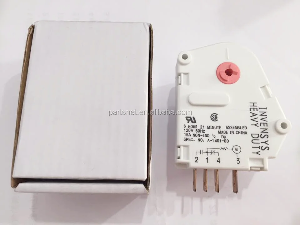
This defrost timer is a genuine OEM replacement part sourced directly from the manufacturer for use refrigerators and freezers. The timer stops the compressor and evaporator fan motor at factory-set intervals. It starts the defrost heater's circuit to melt ice or frost on the evaporator to block airflow. If the defroster timer fails, ice will buildup, and the compressor will not run, which ...

Diagram Page
27.12.2018 · How To Know if a Washing Machine Timer Is Bad. The washing machine timer can be considered the brain that controls the washing machine's systems. Although timers are ruggedly constructed, they ...
Commercial Refrigeration Temperature and Defrost Controls
11.8.2017 · Gm Tbi Tps Wiring Library Of Wiring Diagram Within Throttle Chevrolet Throttle Position Sensor Diagnosis And Repair Help 1996 1998 Throttle Position Sensor Circuit ...
Appliance411 FAQ: How does a Frost Free Refrigerator's ...
Has anybody wired an 8145 defrost timer to a regular five ton a/c straight cool unit installed to a walk in cooler without a solenoid valve and only a cooler t-stat defrost timer wiring Help

DEFROST TIMER CONNECTION! REFRIGERATOR TIMER CONNECTION! DOUBLE DOOR REFRIGERATOR TIMER CONNECTION
Wiring for a single evap freezer system or reach in freezer. Any questions or comments Feel free to ask in the comment section . Thanks for watching 👍. ...
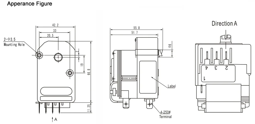
MECHANICAL DEFROST TIMER 8000 Series
Fig. 7. Wiring diagram for systems with pressure switches in series with the contactor and no connection to the defrost control. Fig. 8. Wiring diagram for simple timer applications. CONFIGURATION 1. Connect power. 2. On power up the display will briefly flash the soft-ware version of the DB7110U and then begin cycling between the normal ...

Typical wiring for defrost on a single evaporator freezer
May 18, 2019 · Wiring Diagram – Freezer ½ to 2 HP Single Phase. .. Set the correct time of day on the defrost timer. Do not set a cooler thermostat below the walk-ins design temperature or product Diagram 9 - Typical Wiring Diagram for Single with Defrost Timer Only.Jul 02, · I can increase the defrost time (Grasslin timer), but don't believe it will be ...

LEARN THE HVAC & REFRIGERATION: No Frost Refrigerator Wiring ...
4.11.2018 · anzo tailgate light bar wiring diagram; apexi turbo timer wiring diagram; application of staircase wiring; arc switch panel wiring diagram; arctic snow plow wiring diagram; arduino rs232 schematic; arduino servo motor wiring diagram; asco solenoid valve wiring diagram; atv starter solenoid wiring diagram; atwood rv furnace wiring diagram

DEFROST TIMER CONNECTION! REFRIGERATOR TIMER CONNECTION! DOUBLE DOOR REFRIGERATOR TIMER CONNECTION
Applications and Wiring Diagrams MECHANICAL DEFROST TIMER 8000 Series Customer Service Telephone 1.800.304.6563 Customer Service Facsimile 1.800.426.0804 HVACCustomerService@robertshaw.com www.robertshaw.com www.Uni-Line.com ©2014 Robertshaw 09/14 – 150-2230 RevB For Technical Service Telephone 1.800.445.8299 Facsimile 1.630.260.7294
Defrost Timer - Electrical & In-Line Components - Parts ...
Here is a picture gallery about 20 wiring diagram complete with the description of the image please find the image you need. Paragon defrost timer wiring diagram paragon defrost timer wiring regarding 8145 20 wiring diagram image size 577 x 600 px and to view image details please click the image. 8145 20 8000 series defrost timers the paragon ...

Johor,Johor Bahru (JB),Taman Johor Jaya GR-H61MT TOSHIBA ...
The Latest Paragon® Defrost Timer • Universal Defrost Timers (UDT) • Works with multiple voltages • Removes built up of ice and frost • Easy to install • Simple to program • Part 9145-00 temp terminated • Part 9045-00 time terminated • Available as mechanism only without case - Add "M" to end of part number

Defrost Timer DBZC-825-1GS TMDC825 @ Timer Peti Ais 825 ...
How you diagnose a non-starting compressor depends much upon whether you have a mechanical defrost timer or ADC (Adaptive Defrost Controls.) If you have a fridge with ADC and the lights are on, and the compressor will not start, you need to check if you're getting voltage to the compressor starting components as described in Section 5-3(b).
INSTALLATION DATA 8000 SERIES AUTO VOLTAGE DEFROST TIMER
High Quality Electronic Sankyo Defrost Timer Tmdc621 - Buy ...

China Refrigerator Defrost Timer Sankyo Tmde706sc - China ...

318 ICM DEFROST TIMER | Manualzz
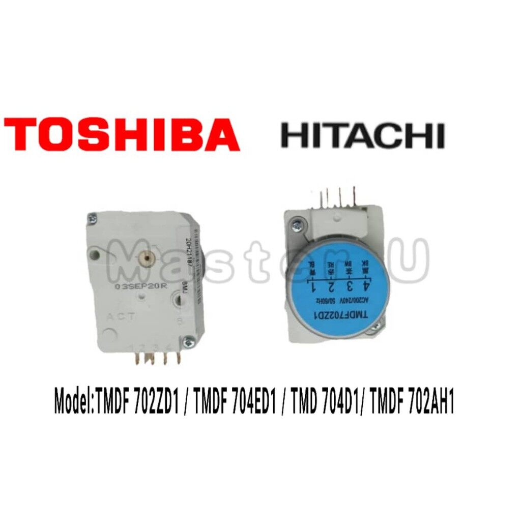
TOSHIBA/HITACHI REFRIGERATOR DEFROST TIMER TMDF702ZD1
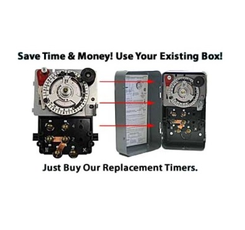
Precision Defrost Timers - Replacements Only

Defrost Timer - Servair Ltd Air Conditioning

Buy Spareplanetâ„¢Defrost Timer Compatible with LG Double Door ...

No frost | D-frost Timer Diagram - Fully4world
Refrigerator Timer / Defrost Timer For Refrigerator ...

paragon 8145 20 wiring diagram Questions & Answers (with ...
TMDF702ZD1 / TMDF704ED1 / TMDE706SC / TMDF603AD1 / TD-20C / ND0804M2PR REFRIGERATOR DEFROST TIMER Refrigerator TIMER

SOLVED: Refrigeration ynit not going into defrost, I need - Fixya

Robertshaw | Products | A769-00

Defrost Timers, description about Defrost Timer TMDE706SA1 on ...
6HOUR Refrigerator Defrost Timer (Peti Sejuk)(6 Hour ...

DEFROST TIMER CIRCUITS SCHEMATIC DIAGRAM SAMPLE AND ...
TMDE309ZC TIMER DEFROST 4HR 9MINS
Remove the fridge defrost timer - Hardware - BrewPi Community

NO FROST REFRIGERATOR ELECTRICITY DIAGRAM - TPTUMETRO


Comments
Post a Comment