41 sysml block definition diagram
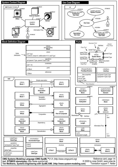
SysML Block Definition Diagram Block Definition Diagram defines the features of a block and any relationships between blocks such as associations, generalizations, and dependencies, in terms of properties, operations, and relationships (for example, a system hierarchy or a system classification tree). Block definition diagrams realise a structural aspect of the model of a System and show what conceptual things exist in a System and what relationships exist between them. The things in a System are represented by blocks and their rela- tionships are represented, unsurprisingly, by relationships. 5.5.1.1 Diagram elements
SysML Block Definition Diagram. Block Definition Diagram defines the features of a block and any relationships between blocks such as associations, generalizations, and dependencies, in terms of properties, operations, and relationships (for example, a system hierarchy or a system classification tree). Block Definition Diagrams are based on UML ...

Sysml block definition diagram
The purpose of Activity diagrams is to specify dynamic system behaviors that Satisfy («satisfy» Dependency) system Functional Requirements using both Controland Object (data) Flows. When properly applied (See Usage Notesbelow) Activity diagrams are recursively scalable and simulatable. SysML Activity Diagram: Top-Level Functions The Block Definition Diagram in SysML defines features of a Block and relationships between Blocks such as Associations, Generalizations, and Dependencies. It captures the definition of Blocks in terms of properties and operations, and relationships such as a system hierarchy or a system classification tree. The SysML internal block diagram uses to model the decomposition of a block or its internal structure such as parts and subsystems; in contrast, a Block Definition Diagram (bdd or BDD) shows Blocks, their contents, and relationships.
Sysml block definition diagram. The purpose of Block Definition Diagrams is to specify system static structures that be used for Control Objects, Data Objects, and Interface Objects. When properly applied (See Usage Notesbelow) Block diagrams are recursively scalable and mathematically (parametrically) simulatable (See Executable Semanticsbelow.) Agile MBSE™ + SysML Expert When shown on a Block Definition Diagram, a Block's notation is as follows. You can show compartments for the Block's roles and properties. To show a compartment: right-click the Block, click Show/Hide Compartments, and then select the check boxes associated with the roles and properties you want to show. Rick Steiner, in Practical Guide to SysML, 2008 6.1.1 Block Definition Diagrams The block definition diagram or "bdd" is used to define blocks in terms of their features, and their structural relationships with other blocks. The block definition diagram header is depicted as follows: bdd [model element type] model element name [diagram name] Block elements can be created using the 'Add Element' option on a Package context menu, or by using the SysML Block Definition toolbox to place a Block on a Block Definition diagram (BDD). It is common for Blocks to appear on multiple BDDs, where each diagram is designed to address the concerns of a particular stakeholder or stakeholder group.
SysML Tutorials for MBSE. SysML Diagram Tutorial (PivotPoint Technology Corp.) SysML tutorial that compares and contrasts all nine (9) SysML diagram types and Allocation Tables. Jan 2019. Modeling with SysML (Johns Hopkins APL) SysML tutorial presentation from INCOSE 2010 conference. PDF format derived from PPT slides. July 2010. SysML: Modeling Element Structure with Block Definition Diagram The block definition diagram Derived from the UML Class Diagram is the most widely-used diagram for modeling the static structure of a system. It is often be used to declare Blocks and their compositional, logical, and generalization / Inheritance relationships. Block Definition Diagrams The most common kind of SysML diagram is the block definition dia-gram. You can display various kinds of model elements and relation-ships on a BDD to express information about a system's structure. You can also adopt design techniques for creating extensible system struc- Block Definition Diagram (bdd): A Block Definition Diagram is a static structural diagram that shows system components, their contents (Properties, Behaviors, Constraints), Interfaces, and relationships.
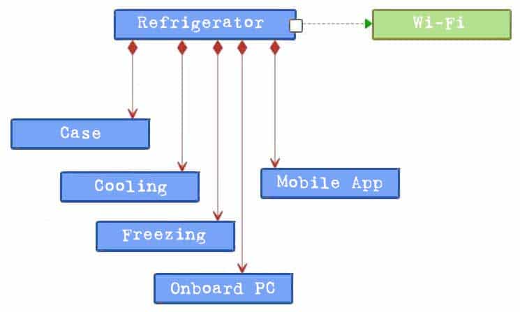
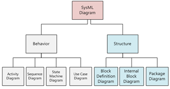
SysML Modelling Language explained Page 4 SysML defines the following diagrams: Structure diagrams o The Block Definition Diagram (BDD), replacing the UML2 class diagram o The Internal Block Diagram (IBD), replacing the UML2 composite structure diagram o The Parametric Diagram, a SysML extension to analyse critical system parameters o The Package Diagram remains unchanged In a SysML Block Definition Diagram, can a single "block" represent both hardware and software? Ask Question Asked 2 years, 9 months ago. Active 1 year, 2 months ago. Viewed 187 times 1 0. In contrast to class diagrams, it seems one can model multiple facets of a system in block diagrams such as software, hardware, entities, etc. ... Drag on the diagram as the size you want. To create a Block (model element only) by Menu: 1. Select an Element where a new Block to be contained. 2. Select Model | Add | Block in Menu Bar or Add | Block in Context Menu. You can use QuickEdit for Block by double-click or press Enter on a selected Block. An Interface block is a special kind of block for typing proxy ports. It has no behaviors or internal parts. Normally, it contains a set of flow properties that can be shown in the flow properties compartment. Visibility representation In SysML, properties and operations of the Block are public.
Block Definition Diagram - an overview | ScienceDirect Topics
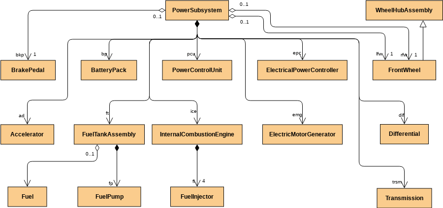
When describing your system structure, you should start from defining Blocks in SysML Block Definition Diagram. Blocks represent the system hierarchy in terms of systems and subsystems. You can model either the logical or physical decomposition of a system, and the specification of software, hardware, or human elements.

Free SysML Block Definition Diagram Tool
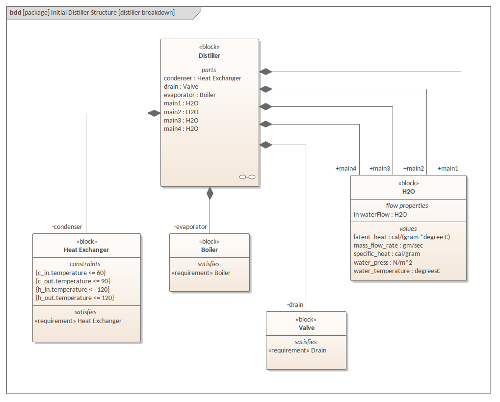
An example of a SysML Block Definition diagram. This diagram shows that the top-level Distiller Block is composed of a number of Parts, namely the Blocks Heat Exchanger, Boiler and Valve. Each Block also shows its Ports, the type associated with the Port and the direction of flow, in or out, of the port. Learn more: Creating Ports and Parts.

Block definition diagram (bdd) for two-DOF robot, specifying ...
What is a SysML Block Definition diagram? Definitions. Block: A Block (notation: rectangle with keyword = «block») represents a system component, a modular structural unit that encapsulates its contents (Properties, Behaviors, Constraints) and supports first-class (i.e., can be drawn and directly manipulated in the model repository) Interfaces. ...
Free SysML Block Definition Diagram Tool
The Block Definition Diagram is the primary kind of diagram you create to communicate structural information about a system. This powerful design technique creates extensibility in your system design by decoupling the clients of services from any specific implementation of a provider of those services. As your stakeholders' requirements evolve over time, you can modify existing providers or ...
SysML-block-definition-diagram-IBM-Rational-rhapsody-of ...
What is a SysML Internal Block Diagram? Definitions. Block: A Block (notation: rectangle with keyword = «block») represents a system component, a modular structural unit that encapsulates its contents (Properties, Behaviors, Constraints) and supports first-class (i.e., can be drawn and directly manipulated in the model repository) Interfaces. ...

Block Definition Diagram (BDD) | Innoslate Help Center
Block Definition Diagram in Cradle. 1. There are two kinds of SysML Diagrams used to specify the structure of the proposed System (i.e., Block Definition Diagrams and Internal Block Definition diagrams). A block used in either type of diagram is a type of 'thing' (e.g., system, subsystem, light, report, organization, human, etc).
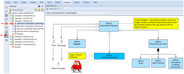
System Context Diagram Block Definition Diagram OMG Systems ...
A SysML Block Definition Diagram defines blocks in terms of their features and inter-relationships. Visual Paradigm Online's online SysML tool lets you create Block Definition Diagrams easily with drag and drop. Whether you're a beginner or a pro, to draw a SysML diagrams is always simple and fast with VP Online.
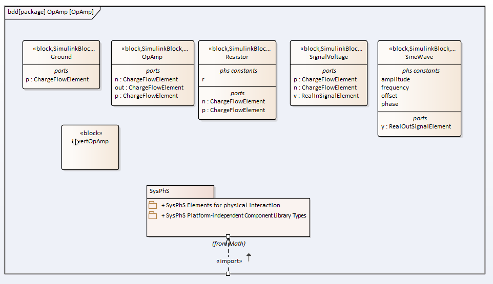
SysPhS Block Definition Diagram - Operational Amplifier ...
SysML Block Definition Toolbox. When you are constructing SysML models, you can populate the Block Definition diagrams using the icons on the SysML Block Definition pages of the Diagram Toolbox.. You can also generate Property elements on the Block, based on the Association relationships created for the Block element.

Block Definition Diagram - StarUML documentation
Die Systems Modeling Language (OMG SysML) ist eine grafische, auf UML 2 basierende, standardisierte Modellierungssprache.Ihre Anwendung findet sie im Bereich Systems Engineering für die Modellierung verschiedener komplexer Systeme. Die Menge der in SysML definierten Diagramme besteht aus einer Untermenge von Diagrammen, die sich aus in UML 2 definierten Diagrammen ableiten lassen, ergänzt ...

A SysML Operational Domain Model | Enterprise Architect User ...
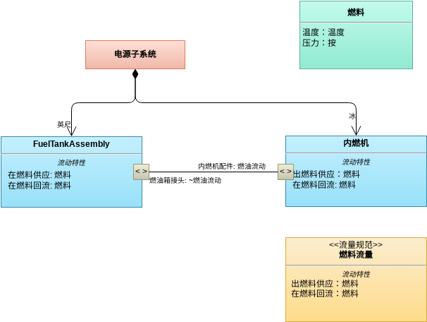
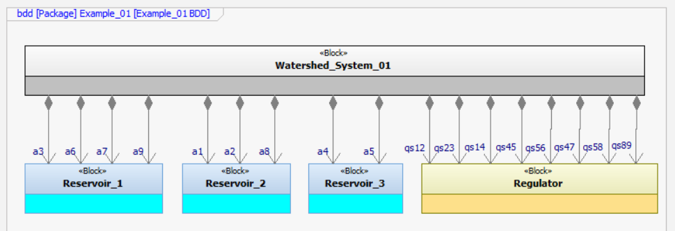
Block Definition Diagram (bdd) A «block» is a modular unit of structure in SysML that is used to define types of physical entities (e.g. system, system component part, external systems, or items that flow through the system), as well as conceptual entities or logical abstractions.

SysML Block Definition, Internal Block & Package Diagrams ...
The SysML internal block diagram uses to model the decomposition of a block or its internal structure such as parts and subsystems; in contrast, a Block Definition Diagram (bdd or BDD) shows Blocks, their contents, and relationships.
Free SysML Block Definition Diagram Tool
The Block Definition Diagram in SysML defines features of a Block and relationships between Blocks such as Associations, Generalizations, and Dependencies. It captures the definition of Blocks in terms of properties and operations, and relationships such as a system hierarchy or a system classification tree.
What is a Block Definition Diagram? - Smartpedia - t2informatik
The purpose of Activity diagrams is to specify dynamic system behaviors that Satisfy («satisfy» Dependency) system Functional Requirements using both Controland Object (data) Flows. When properly applied (See Usage Notesbelow) Activity diagrams are recursively scalable and simulatable. SysML Activity Diagram: Top-Level Functions
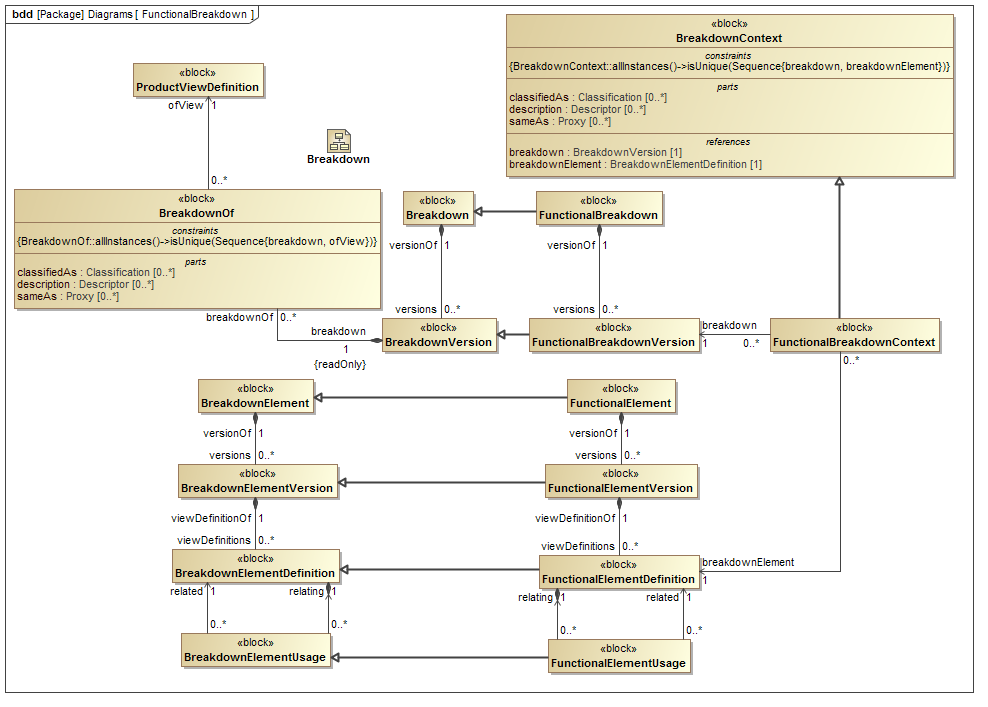
Template: FunctionalBreakdown
SysML Block Definition, Internal Block & Package Diagrams ...
Altova UModel 2022 Professional Edition

SysML Block Definition, Internal Block & Package Diagrams ...

SysML Block Definition Diagram (BDD) illustrating the SNR ...
Is Capella a SysML Tool ?

Template: SchemeEntry

Defining Blocks in Block Definition Diagram

Internal Block Definition Diagram - displaying operations ...
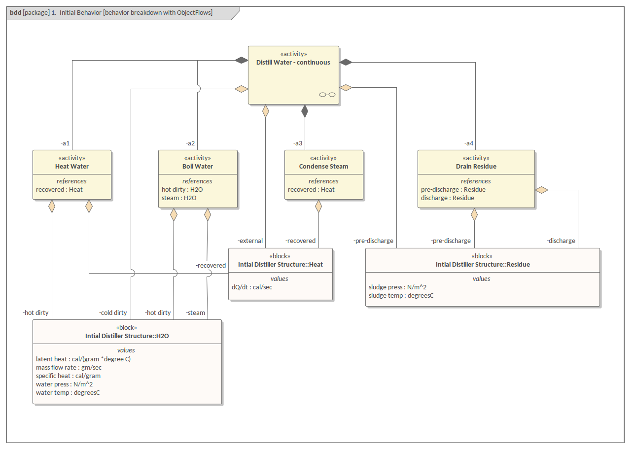
SysML Block Definition Diagram - Distiller Behavior Object ...

Block Definition Diagram of the System in SysML | Download ...
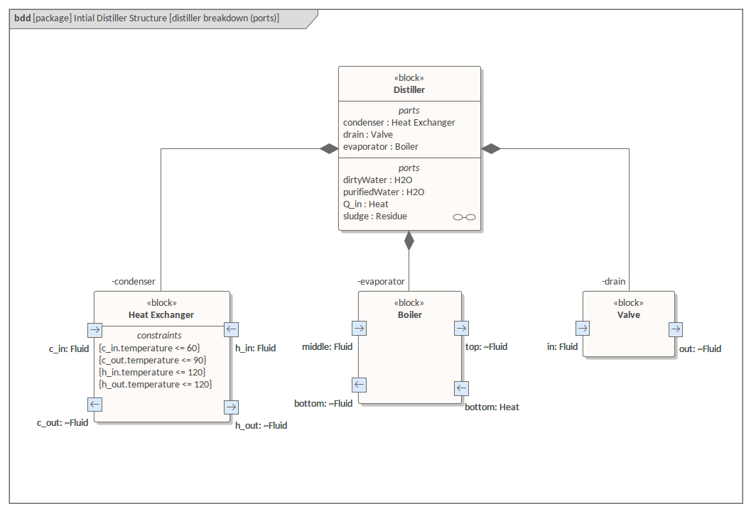
SysML Block Definition Diagram - Distiller - Ports ...
SysML Block Definition Diagram of the ACAS XU System ...
SysML FAQ: What is an Internal Block Diagram (IBD)?
Block definition diagram (SysML diagram)

SysML block definition diagram of example | Download ...
SysML Block Definition Diagram | Webel IT Australia

Creating Block Definition Diagrams for the System Context with Papyrus SysML by Jan Peleska
SysML FAQ: What is a Block Definition Diagram (BDD)?

A SysML block definition diagram illustrating the parts ...
Block Definition Diagram | 3SL Cradle® Software North America
SysML Block Definition Diagram - Distiller | Enterprise ...
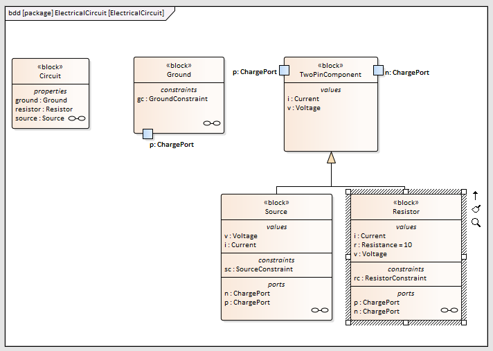
SysML Block Definition Diagram - Electrical Circuit ...

Build Diagrams

Block Definition Diagram | Astah in 5min

Block Definition Diagram (BDD)

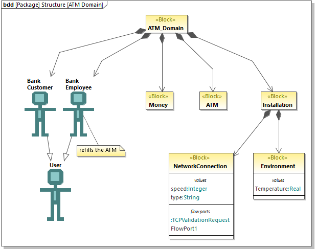
Structure Block Definition Diagram (BDD)
Figure 3 from Formalizing and verifying compatibility and ...


Comments
Post a Comment