41 transmitter block diagram
Draw a block diagram of a high or low-level AM transmitter, giving typical signals. at each point in the circuit. Discuss the relative advantages and disadvantages of high and low-level AM transmitters. Figure: Block diagram of MSK transmitter. The block diagram is shown below: Figure: MSK receiver block diagram. Simulation Model.
The power amplification of the radio signal is carried out in the final stage of the block diagram. It makes the signal stronger so that it can be transmitted ...
Transmitter block diagram
The RTD Temperature Transmitter is a 4 to 20-mA current-loop reference design that supports RTD Low Drift Oscillator. Precision Temp Sensor. Block Diagram. CS Sclk din dout/drdy drdy. A.M. Transmitter Tutorial - Block Diagram - Electronics Circuit and Tutorials - Hobby Science Projects - Modulation enables low frequency audio signals to be radiated long distances. You can see, in the block diagram of the FM Transmitter, the first block is the Microphone. The microphone is a Transducer which can convert the sound energy into an audio signal in the form of electrical energy. So microphone is a source of an audio signal.
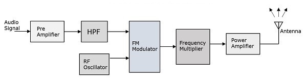
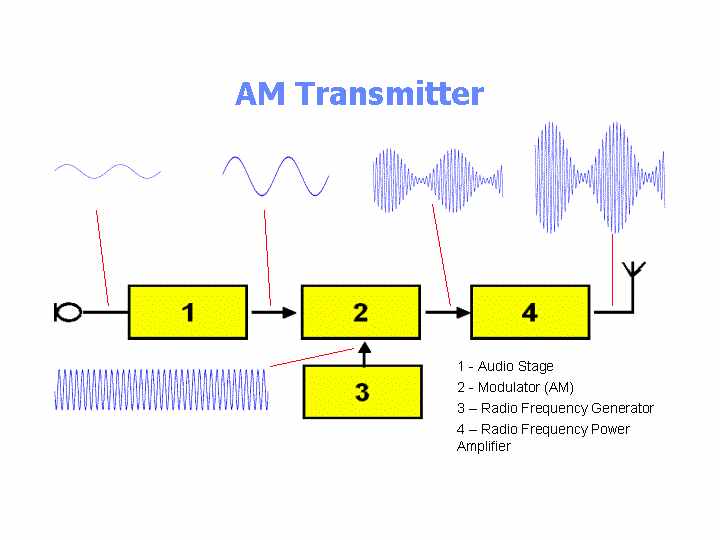
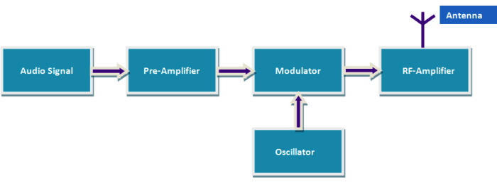
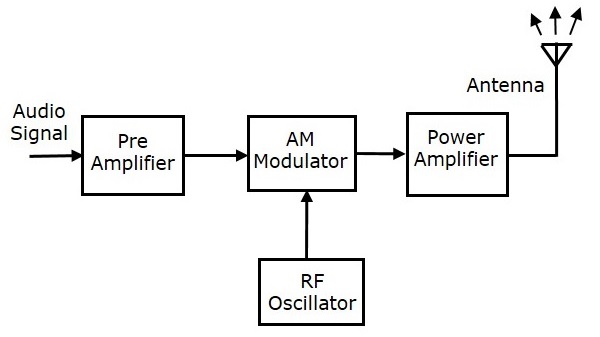
Transmitter block diagram. PCM Transmitter Block Diagram Here is a block diagram with explanation of a Pulse Code Modulation (PCM) transmitter. To transmit an analogue signal in digital form, we must first sample it in order to convert it into a digital form. The sampling gate is the block that continuously samples and stores the incoming analogue signal. The transmitter has the same basic layout as any AM transmitter, though it may differ in specifics. A block diagram of the as-built unit appears below. Refer back to this diagram as the parts are... Block diagram of Pulse Code Modulation. The figure below shows the block diagram representing a PCM system. It is basically composed of a transmitter, a transmission path and a receiver. The block diagram of AM transmitter is shown in the following figure. The working of AM transmitter can be explained as follows. The audio signal from the output of the microphone is sent to the pre-amplifier, which boosts the level of the modulating signal. The RF oscillator generates the carrier signal.
The following image shows the block diagram of the FM transmitter and the required components of the FM transmitter are; microphone, audio pre-amplifier, modulator, oscillator, RF- amplifier, and... ... PWAM transmitter is shown in detail in Fig. 5. It contains three main building blocks: a PWM ... Maximizing the minimum pulse difference DT Pmin is another important eye diagram consideration. A block diagram description of an FM transmitter follows. Figure 2. FM Transmitter Block Diagram. As the block diagram above illustrates, the integration of a message signal results in an... Transmitters with block diagrams General AM transmitter and theri function General FM transmitter and theri function General PM transmitter and theri function working of each blocks Plezzz like and...
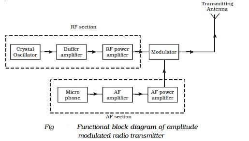
Aug 5, 2012 - Transmitters that transmit AM signals are known as AM transmitters. These transmitters are used in medium wave (MW) and shortwave (SW) ... Transmitter Block Diagram (... page 42 - Directional coupler page 43 - Harmonic filter page 44 page 45 page 46 - Figure 3-21. The block diagram of QAM transmitter and receiver also has been explained here. Quadrature Amplitude Modulation (QAM)/ QAM Transmitter and QAM Receiver Block Diagram. Draw the schematic diagram of your intended transmitter and explain its function in brief. — Draw the schematic diagram of your intended transmitter ...
A.M. Transmitter Tutorial - AM Transmitters - Block Diagrams ...
Most direct conversion (DC→RF) transmitters are realized ThuesipnegrfotrhmeanIc/eQofmaixdeirrecdt-icsocnuvsesrseido.n TtrawnsomIittaerndis QtypDicaAllCy...

Block diagram and operation of transmitter unit of mobile ...
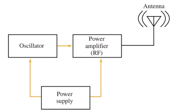
A block diagram of a simple continuous wave (CW) transmitter is shown in Figure 6. The first block is the conventional crystal oscillator and then the final power amplifier. A power supply is provided for the oscillator and the final power amplifier. Figure 6. A block diagram representing various stages of a basic continuous wave radio transmitter.
Radio Transmitter and Receiver | Working | Block Diagram ...
The information and diagrams contained in this guide are the exclusive property of Blonder Tongue Laboratories, Inc., and may be reproduced, published for specifying, designing a RF system, or...

Basics of Smart Transmitters ~ Learning Instrumentation And ...
Block diagram of AM transmitter and receiver with explanation. AM Transmitter : Transmitters that transmit AM signals are known as AM transmitters.

Communication Protocols Assignments: Block diagram of AM ...
Draft 2. Updates for initial review feedback and addition of several example timing diagrams for PCI Express 3.0 related signals. Updated for Draft 2 feedback from various reviewers.
Analog Communication - Transmitters
Fig.1 shows the block diagram of a general communication system, in which the different functional In short, we can say that inside the transmitter, signal processings such as restriction of range of...
1201774 FM Transmitter Block Diagram Block ITI HONG KONG
Block diagram of a low level FM broadcast transmitter is shown in figure. The master oscillator generates the RF signal (carrier) required for modulation. Master oscillator is generally a well defined LC oscillator. The buffer amplifier is used to make the oscillator frequency free from the loading of the next stages.
Draw the block diagram and explain the various stages of an ...
Transmitter Block Diagram. 8 bits. • Data can be transmitted and received during these blocks, except for a transient period at the beginning of the block.

Satellite Earth Station Block Diagram
Pasternack’s library RF and microwave block diagram are designed to provide engineers and designers with examples of common RF systems schematics while illustrating the RF products and where they fit into the system’s design.
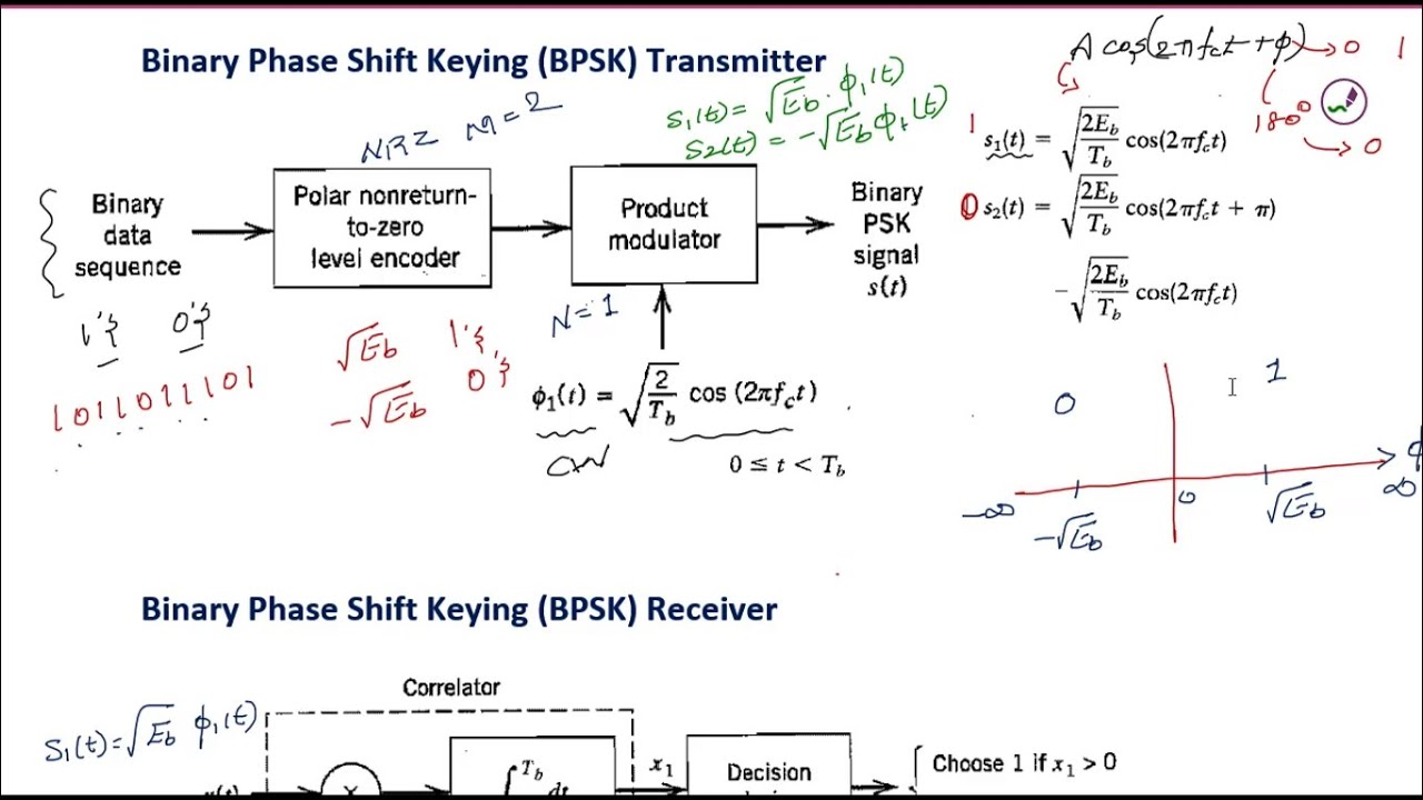
BPSK transmitter and receiver | Binary Phase Shift Keying block diagram | BPSK DIGITAL COMMUNICATION
The block diagram of an FDM receiver is shown in fig3. The block diagram of FM transmitter is shown in the following figure. Each signal that needs to be sent over a communication channel undergoes modulation with various carrier frequencies as shown clearly in the diagram below. Fm Transmitter Block Diagram And Explanation Of Each Block Pdf.
Transmitter Block Diagram
Simple Two Stage FM Transmitter - This is one of the most simple FM transmitter circuits you can try out with a schematic diagram, a design of FM demodulator, and working of PLL with block diagram.
TRANSMITTERS | Home
Fig. 5 shows a block diagram of a CW type of transmitter. We have included fre- quency doublers and amplifiers to provide a general idea of what might be found in a transmitter circuit. The frequency multipliers could be triplers or even quadruplers, if that would aid us in arriving at the desired transmitting frequency.
DIY Simple FM Transmitter Circuit without Inductor and Trimmer
Radio Transmitter Block Diagram This block diagram of a radio transmitter in a communication system is very simple and basic. It is generalised for AM and FM types of modulation, and consists of four subsystems. Communication is the transfer of meaningful information from one location to another.
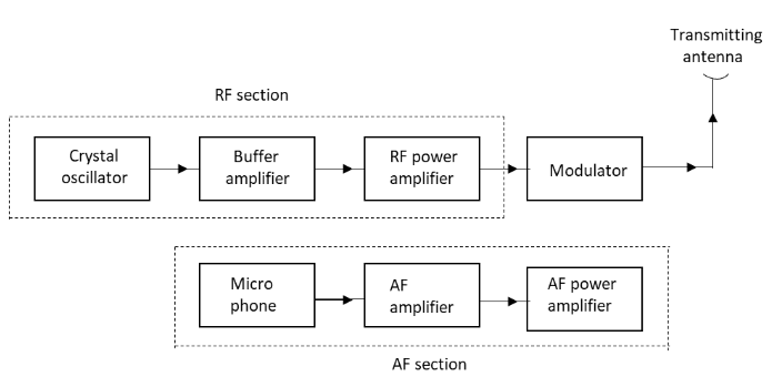
Radio transmission - AM, FM transmitter and AF, RF section
13.2 Linear Block Codes (13.1) 604 Matrix Representation of Block Codes Syndrome Decoding 608 Cyclic Codes 611 M-ary Codes 616. 13.3 Convolutional Codes (13.2) 617 Convolutional Encoding...
Block diagram of a basic RF transmitter (Tx) | Download ...
Block Diagram. OSC Signal Descriptions. External Crystal / Resonator Connections. Chapter 40 Universal Asynchronous Receiver/Transmitter (UART1 and UART2).

Draw the block diagram of Amplitude Modulated (AM) Radio ...
The transmitter block diagram is shown in Figure 1. The input, LC_BYP , Bypassing 8B/10B Encoding and Decoding APPLICATION NOTE Figure 1. Transmitter Block Diagram RATE , a serial backplane...

Schematic diagram of transmitter and receiver. | Download ...
Block diagram of a low level FM broadcast transmitter is shown in figure. Frequency Modulation is the process in which the frequency of the carrier signal is varied by the modulating signal while the amplitude remains constant. The exciter section contains the carrier oscillator reactance modulator and the buffer amplifier.

Digital Transmitter - an overview | ScienceDirect Topics
Figure 2-2 NM 7013 Transmitter Block Diagram part 2. ©1999 Navia Aviation AS. TRANSMITTER DESCRIP-. Block Diagram: Channel select cou. Normarc 7013.

Basic Single Sideband SSB Operation - Satellite Communications
A traditional RF transmitter system and amplifier block diagram would have the baseband generation system where the signal is created with its modulation and up-converted to the final frequency.
TV - Television Transmission
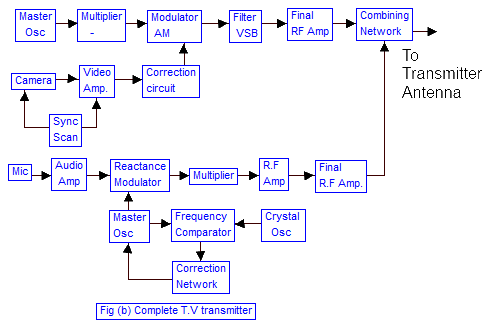
Sep 1, 2016 - The basic television Broadcast transmitter block diagram is shown in figure (a). The block diagram can be broadly divided. Complete TV transmitter Block Diagram.

Field Transmitter: Temperature Sensor Block Diagram ...
You can see, in the block diagram of the FM Transmitter, the first block is the Microphone. The microphone is a Transducer which can convert the sound energy into an audio signal in the form of electrical energy. So microphone is a source of an audio signal.

Pin on Process Technology
A.M. Transmitter Tutorial - Block Diagram - Electronics Circuit and Tutorials - Hobby Science Projects - Modulation enables low frequency audio signals to be radiated long distances.

Block Diagrams - an overview | ScienceDirect Topics
The RTD Temperature Transmitter is a 4 to 20-mA current-loop reference design that supports RTD Low Drift Oscillator. Precision Temp Sensor. Block Diagram. CS Sclk din dout/drdy drdy.
TRANSMITTERS | Home

TV Transmission- TV Transmitter Block Diagram|Television ...

Electrical and Electronics Engineering: FM transmitter Block ...

Transmitter vs Receiver | Transmitter types,Receiver types ...

transmitter-block-diagram - Hacked Gadgets – DIY Tech Blog
Analog Communication - Transmitters
Transmitter and Receiver Block Diagram | Download Scientific ...
Radio Transmitter and Receiver | Working | Block Diagram ...

B-2 || Block diagram of AM & FM Transmitter and Receiver || Block diagram of AM & FM Receiver

Arduino FM Transmitter - Engineering Projects

SR119 Remote Control Transmitter Block Diagram Nuzon ...

AM Transmitters | Block diagram, Transmitter, Communication

Block diagram for transmitter and receiver side | Download ...

802.11ac Transmitter Block

Block Diagram Transmitter Receiver × 2 Transmitter Power ...
Draw the block diagram of Amplitude Modulated AM Radio class ...
TMU925 UHF DTV ATSC 1KW TO 2.5 KW TRANSMITTER FAMILY Block ...

4.4 Bluetooth Transmitter. - Drum Pants


Comments
Post a Comment