42 control 4 wiring diagram
PDF Configurable Wired Keypad Installation Guide ctrl4.co/buswiring Wiring diagrams For bus wiring details, refer to the Keypad Bus Wiring Guide(ctrl4.co/buswiring). Operation and configuration On initial power up, all status LEDs on the keypad will illuminate green, indicating that the device has power. Until the keypad has been configured into a Control4 system, it will not control any loads. Emcp 4.2 Wiring Diagram - schematron.org The EMCP 4 supports RS and TCP/IP SCADA Data Links. CAT EMCP II & II+ Installation Guide 1. Unpack the monitor, antenna and the data/power cable. The 25 pin connector plugs onto the front of the Omnimetrix® monitor. This cable includes wires to power the monitor as well as wires for alarm inputs, relay outputs and analog inputs.
PDF Control4® Panelized Lighting: Reference Guide for Electricians Control of loads in a panelized lighting system is achieved with low-voltage keypads, located in key areas throughout the home or business. Low voltage cabling and keypads are typically installed by the Control4 Dealer. Figure 1. Line-Voltage Infrastructure Control4® Panelized Lighting: Reference Guide for Electricians 1 2 Figure 2.
Control 4 wiring diagram
Control Panel Wiring Diagrams - Wiring Diagram and ... Wiring Diagram Of The Marx Control Panel And Charging Components Scientific. Self adhesive wiring diagram for control panel rangvishwa enterprises id 10541553097 basic electrical design of a plc diagrams eep bernini 160kva ats the be28 panels are manufactured in range 15 up to configuration features an alarm output relay and two configurable ... Control 4 Wiring Diagram - elman10.blogspot.com Below are the image gallery of Control 4 Wiring Diagram, if you like the image or like this post please contribute with us to share this post to your social media or save this post in your device. Control 4 Wiring Diagram. Control 4 Wiring Diagram. Control 4 Wiring Diagram. Control 4 Wiring Diagrams - Wiring View and Schematics Diagram Control4 Panelized Lighting Reference Guide For Electricians 8 Channel Relay Wiring Guide Control4 Model Acirc Euro Cent C4 Din Rel E Diagrams Use These Pdf Doent Control4 C4apdkd Adaptive Phase Dimmer Keypad User Manual Control4 Ldz1011 Ldz 101 X Controllable Dimmer User Manual Wirelessdimmer
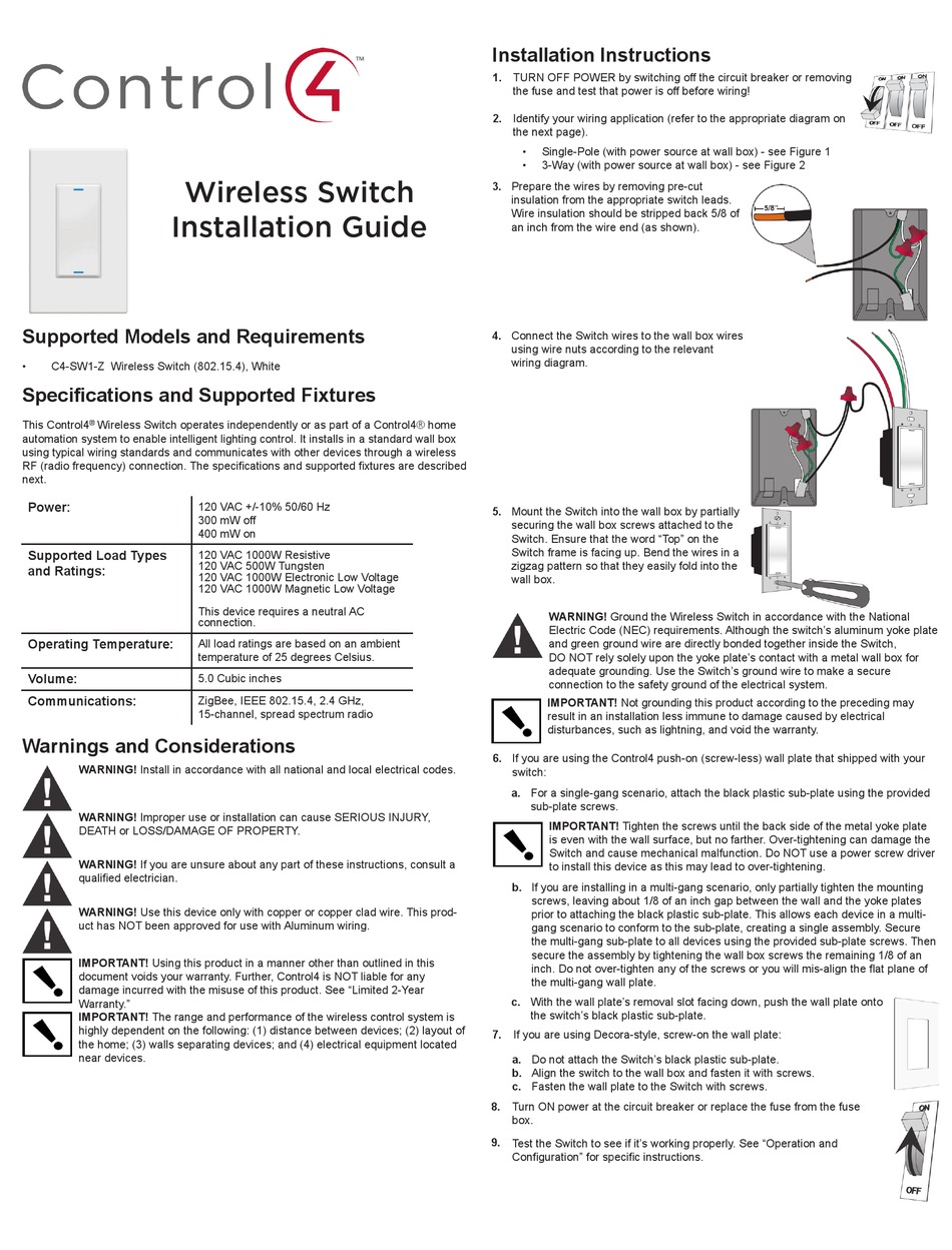
Control 4 wiring diagram. 4 Wire PC Fan - ElectroSchematics.com However, the 4-wire fan is a little different as it has the fourth 'control' wire to input a signal to the fan that commands it to speed up or speed down. Simply, a 3-wire fan reports its speed, and a 4-wire fan lets regulate its speed by an external signal, usually coming from the motherboard. Control4 Ldz-101 Wiring Diagram 3 Way Switch installation guide supported models ldzw wireless dimmer (white) ldzb wireless dimmer (black) 3 identify your wiring application and see the appropriate diagram in "sample wiring (control4's 3-way-switch solution) where the power is first routed to the wall box, do the following. wiring diagram for 3 speed ceiling fan switch with wiring diagram … Control4 Ldz-101 Wiring Diagram 3 Way Switch Identify your wiring application and see the appropriate diagram in "Sample Wiring . way- switch solution) where the power is first routed to the wall box, do the following: 1. Wire. (C4-KA-xx), the wire connecting the Auxiliary Keypad to the switch must not exceed and communicates to the Control4 system using a wireless connection. Powerflex 4 Wiring Diagram The block diagram below highlights the primary.View and Download ALLEN BRADLEY PowerFlex 4M user manual online. FRN 1 Series, FRN 2 Series, Adjustable Frequency AC Drive. PowerFlex 4M Controller pdf manual download. The examples and diagrams in this manual are included solely for illustrative PowerFlex 4 User Manual, Publication 22A-UMJ-EN-E.
PDF 8-Channel Dimmer Wiring Guide - Control4 Black Line Red Load Grey Neutral Green Earth Ground Blue Ethernet Figure 1. Wiring in Control4 Panel Wiring Diagrams Use the Control4® 8-Channel Dimmer wiring diagrams along with the 8-Channel Dimmer Installation Guide to install 8-Channel Dimmers. About this Document Part Number: 200-00247, Rev A 1/17/2013 Control 4 Switch Wiring Diagram - Wiring Diagram And ... Control 4 Electrical Wiring Home Automation Diagram Wire Cable More information ... More information Control 4 Switch Wiring Diagram - Wiring Diagram And Schematics Find this Pin and more on Electrical wiring by Ironmtnmechanical. Electrical Switch Wiring Floating In Space Three Way Switch Shop Lighting Ceiling Fan Wire Lights Creative Home Decor Control4 Essential Lighting Wiring Diagrams Essential Forward Phase Dimmer, 120V (White) Installation Guide. Essential Lighting Professional Wiring Guide. Essential Lighting Comparison. Essential Switch, 120V/277V (White) Data Sheet. Essential Switch, 120V/277V (White) Installation Guide. Plug-In Outlet Dimmer Data Sheet. Plug-In Outlet Dimmer Installation Guide. PPC-4 Thermal Post Purge Kit Installation Manual & Wiring ... April 10, 2019. Super Admin. Installation Manual and Wiring Diagram for model PPC-4 Thermal Post Purge Kit. English. previous post: SC100 Installation Instructions. next post: PPC-5 Electronic Post Purge Kit Installation Manual & Wiring Diagram.
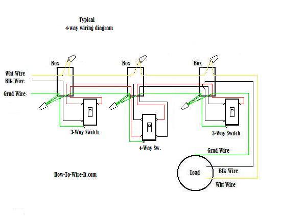
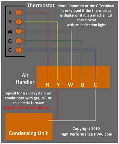
PDF Essential Lighting Wiring Guide - Control4 This diagram shows a sample 4-way wiring configuration using an Essential Forward Phase Dimmer (C4-V-FPD120) or Switch (C4-V- SW120-277) with two Essential Auxiliary Keypads (C4-V-AUX). Daisy-chain each additional Auxiliary Keypad by extending the Ground, Traveler, and Neutral to each keypad. 4-way configuration Emcp 4.2 Wiring Diagram Emcp 4.2 Wiring Diagram. 5 EMCP AND ELECTRICAL DIAGRAMS. sensors will typically be wired to the engine ECM and the EMCP 4 will get that information from the engine. EMCP Auto-start control panel (upgraded to NFPA 11 0) .. 2-wire, 3-wire and 4-wire RTD inputs. Three Phase Wiring Diagram. Control4 Thermostat Wiring Diagram - schematron.org This Control4® Wireless Thermostat enables intelligent HVAC control as part of a Changing this setting is described in Step 14, "Installation Instructions. Control 4 CCZ-T1-W Manual Online: Sample Wiring Configurations. The next several pages provide sample Thermostat connections and configurations for your. Ddec 4 Wiring Diagram - schematron.org The wire. ecm wiring diagram car cable and detroit diesel series 60 best, ddec iv wiring diagram series 60 youtube lively 4 ecm, ddec 4 ecm wiring diagram ii.a DDEC II to DDEC IV conversion is made on a vehicle using the DDEC II cruise control feature.
PDF Basic Wiring for Motor Contol - Eaton control circuit may not be at the same voltage as the power circuit. When the voltage of the control and power circuits is the same, it is referred to as Common Control. If the volt-ages are different, it is called Separate Control. Figure 4. Typical Starter Wiring Diagram — Three-Phase Separate voltages supplied by different voltage sources.
Control 4 Wiring Diagrams - Wiring View and Schematics Diagram Control4 Panelized Lighting Reference Guide For Electricians 8 Channel Relay Wiring Guide Control4 Model Acirc Euro Cent C4 Din Rel E Diagrams Use These Pdf Doent Control4 C4apdkd Adaptive Phase Dimmer Keypad User Manual Control4 Ldz1011 Ldz 101 X Controllable Dimmer User Manual Wirelessdimmer
Control 4 Wiring Diagram - elman10.blogspot.com Below are the image gallery of Control 4 Wiring Diagram, if you like the image or like this post please contribute with us to share this post to your social media or save this post in your device. Control 4 Wiring Diagram. Control 4 Wiring Diagram. Control 4 Wiring Diagram.
Control Panel Wiring Diagrams - Wiring Diagram and ... Wiring Diagram Of The Marx Control Panel And Charging Components Scientific. Self adhesive wiring diagram for control panel rangvishwa enterprises id 10541553097 basic electrical design of a plc diagrams eep bernini 160kva ats the be28 panels are manufactured in range 15 up to configuration features an alarm output relay and two configurable ...









Comments
Post a Comment